Diagnosing the Cause of the blown CNC components
After some investigation, it turned out that more than the FET was blown and the 7812 voltage regulator was gone, along with the fuses. So I had to determine how this happened.
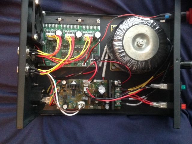
My next step was to gain a better understanding of the 555 timer based PWM circuit driving the FET. Going back to the teardown, there are two boards. The one above is the stepper control and computer interface board. This board was not affected.
The board below, with the big green screw terminals is the power and spindle control board. The problems are all on this board, and I will be referring to this board for the rest of the write up.
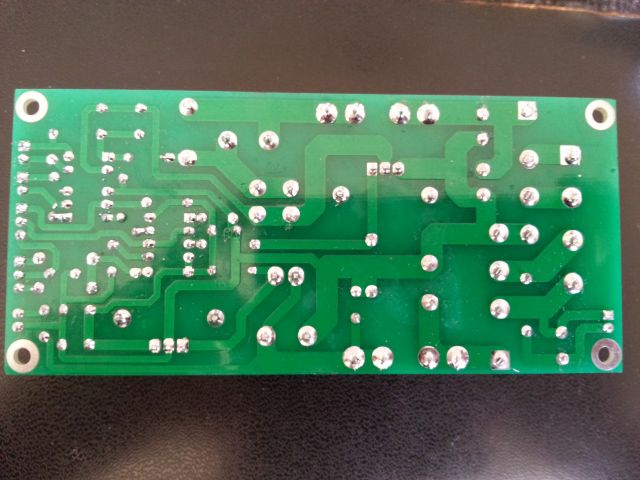
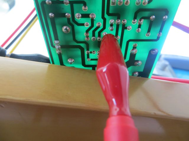
After removing this power board, I got a series of photos of its underside. Since it appears to be a one sided board, this will allow me to trace it in more detail.
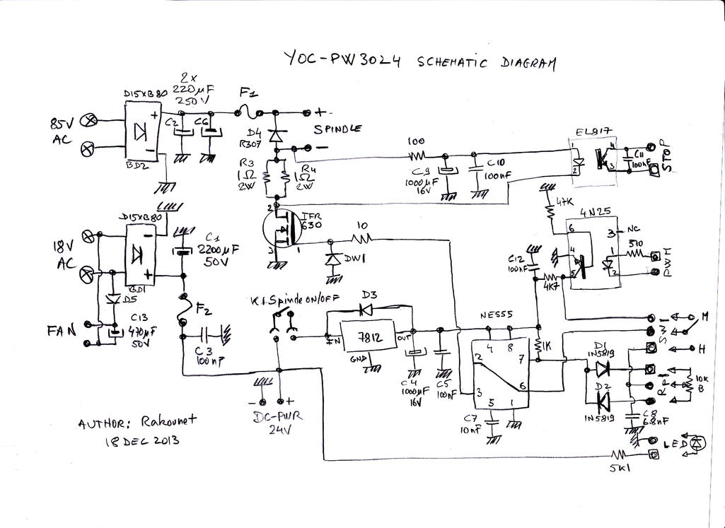
After my previous teardown, I found a few people had traced out fairly similar circuits for the board already so I can then cross reference this, taking into account that it may be slightly different.
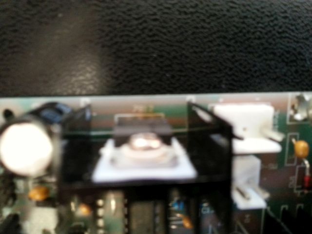
The damage was severe enough to leave a great big crack in one of the devices cases. This indicated that something had pulled a large amount of current through it.
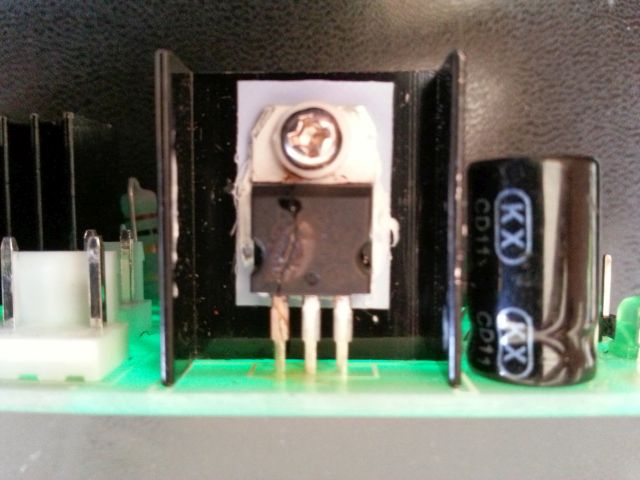
The 7812 was the part with the most damage.
After the teardown and ordering the new parts for my board, I started by replacing the obviously damaged 7812. At this point I bought a few tubes of spares: 7812’s, 555’s, replacement fuses and replacement FETs. This way I was ready to handle anything.
I tried powering the board but the spindle did not move. I sat on the problem for a while before trying to understand the board better. This meant learning a whole bunch of stuff about analogue electronics, power circuits, 555s and op-amps oh my!
So I spent a few weeks playing with the 555, watching eevblog tutorials on op amps and power supply design. I got a simple LED and 555 in stable mode going. I figured out current sense and voltage regulators.
Then I looked at the board and it’s schematic and started seeing the circuit blocks.
The Parts
- 12v regulated supply
- pwm from a 555
- FET motor control
- High voltage/high current supply for the motor
- current sense.
Probing and tracing
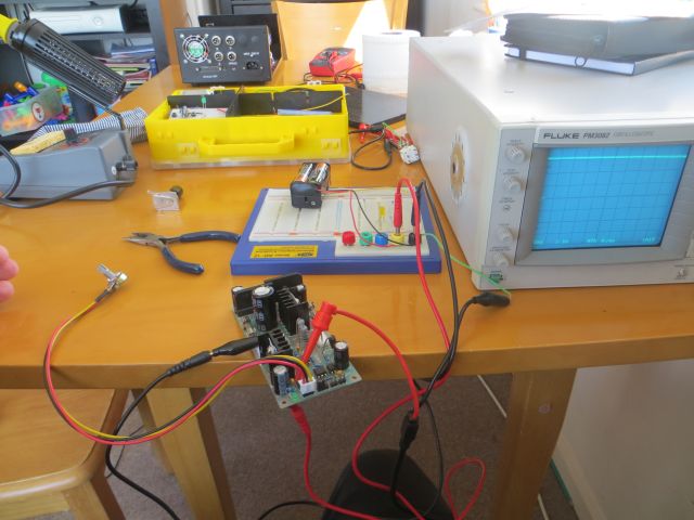
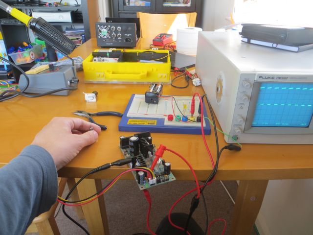
Now I had some parts, and some background, I decided to start by debugging it with an oscilloscope and a small rig. I used 4xAA batteries delivering 6v as a supply, and clipped it onto the board. I connected the batteries to the ground, +ve rails for the low voltage side, where the 7812 output would be.
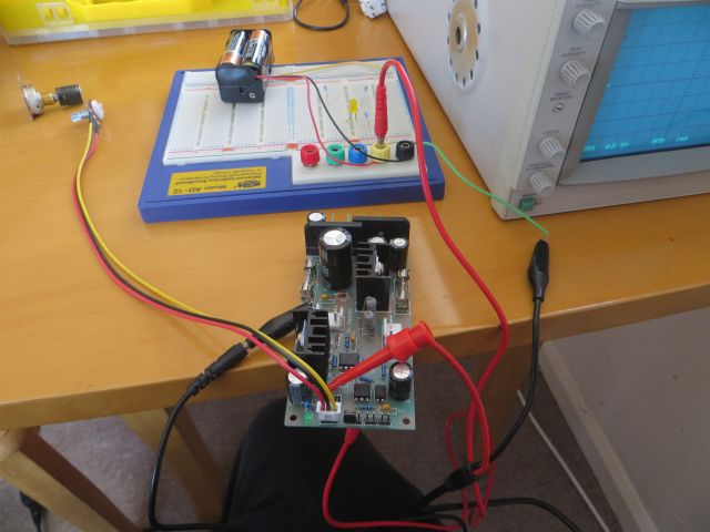
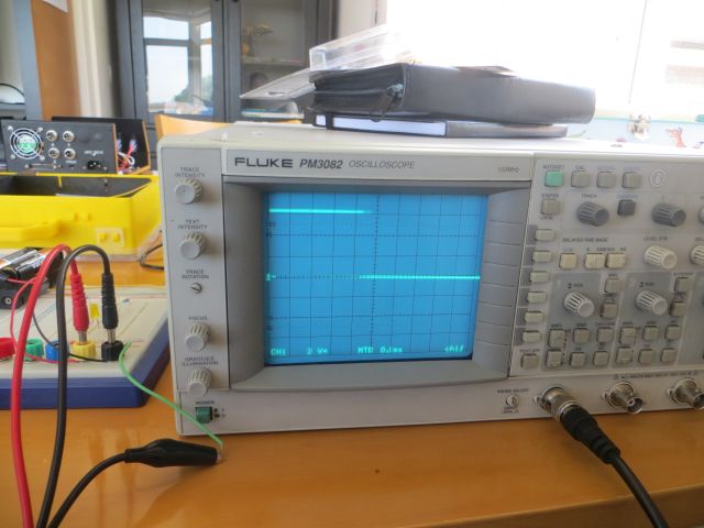
I then plugged in the pwm potentiometer, and hooked up my scope probes to it. What I first saw is this:
Its worth explaining this flat line. This would have pulled all the current through the 7812, kept the FET turned on, and spun the spindle as fast as it would go. This is not good - it would have blown itself again immediately.
The 555 for pwm was charging through one diode and discharging through another - each via the potentiometer - the large spindle speed dial. The proportion of one side to the other should exactly control the PWM duty cycle.
If I nudged the pot I could get the PWM traces, but they were wrong:
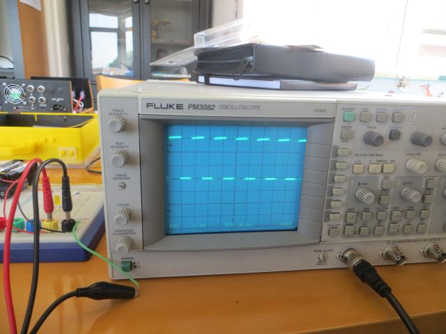
I have to squash the potentiometer body tightly like the image below to get a regular trace:
I took a video of this part of the diagnosis:
My next task is to find a suitable potentiometer, or a place to mount it.
Links
I have come across a number of sites with people spending time on this machine
http://lab.whitequark.org/notes/2014-02-11/cnc3020t-fixing-power-supply/