Attaching a Joystick or 2 Analog Sensors to a Nodemcu
The ESP8266 is one of my favourite devices. I wanted, for various projects, to attach a Joystick to it.
A wireless controller with my own code on it would be an ideal way to control a robot.
However, the joystick has 2 analog outputs, and the esp8266 has only 1 ADC (analog to digital converter).
Clearly I’d have to be a bit sneaky if I wanted to interface them.
You can find the code for this on Github.
Materials
(paid links)
A 2-Axis analog joystick
A NodeMCU ESP8266
A breadboard and some jumper wires
A couple of transistors - I used 2N3904’s, but any NPN transistor will do. A selection box may be a good idea if you are starting the hobby.
Two 2.2k resistors - I used 1/4 watt, but 1/8 watt will do.
The Circuit
So here are detailed notes on the build. First - the joystick, as a circuit diagram, ignoring the switch, looks like this:
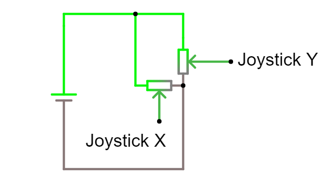
Using the joystick circuit diagram, we are able to establish that ground and voltage on the outputs are shared, so we need some way to selectively consider one output, while not being effected by the other. I looked at some other options (discussed in the video) and my simplest was to use 2 transistors. Note - another method using 2 resistors and a bit of calibration has also been proposed by a viewer.
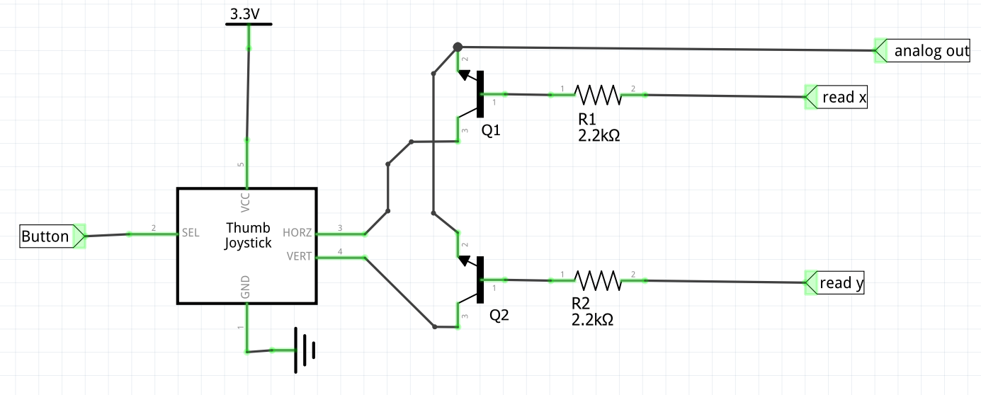
The diagram is somewhat after the fact, I had the idea and built it to experiment with it.
I’ve made a Fritzing version of the breadboard so a reader can reproduce my result:
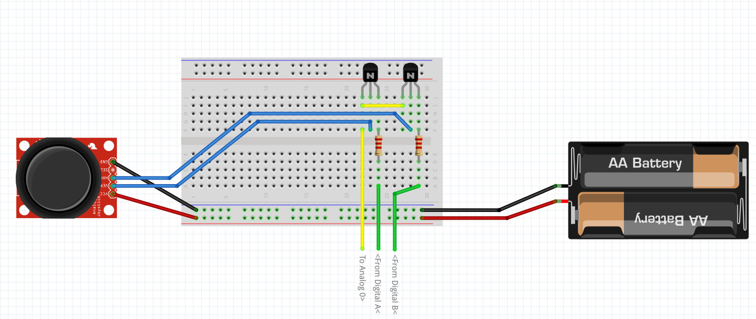
As suggested in the video any NPN transistor will do - I used C series TO92 transistors for this. The point being it’s working in a low voltage - 3.3v, and the switching speed is not particularly demanding either.
The TO-92 transistors are recommended because they are nice for breadboarding.
The simulation file can be used in CircuitJS to simulate the transistor behaviour.
CircuitJS is an in browser electronic circuit simulator, and is a rather awesome toy to play with.
The Code
The code is run in the NodeMCU Lua interpreter - and the whole source is in the github repo as joystick_read.lua.
First I define the pins
    local read_x = 5
    local read_y = 6
    local duration = 500    --> In millis
So read_x has to be high for the ADC to be reading the X axis, and read_y to read the Y axis. Having both high makes no sense, and I may do a follow up using an additional transistor to make an IO pin a toggle for these.
Next is a simple init function - just to put stuff in the right state:
    -- Initialise the pins
    function init_joystick( read_x, read_y )
        gpio.mode(read_x, gpio.OUTPUT)
        gpio.mode(read_y, gpio.OUTPUT)
        gpio.write(read_x, gpio.LOW)
        gpio.write(read_y, gpio.LOW)
    end
Then the function that does stuff… I’ll break this one down somewhat.
function read_joystick( read_x, read_y )So I’m passing the two pins in - I suppose they are defined globally, but this allows the possibility of it being a library.
To read the data, we must set the read_x pin to high, so the transistor connected to X will turn on and allow the X signal through to the ADC:
        gpio.write(read_x, gpio.HIGH)
        local x = adc.read(0)
We then need to swap - ensuring we bring read_x low again, read_y HIGH and the getting data from the ADC again:
        gpio.write(read_x, gpio.LOW)
        gpio.write(read_y, gpio.HIGH)
        local y = adc.read(0)
We then need to put read_y LOW again for the next time we use it, and return the two points as a table
        gpio.write(read_y, gpio.LOW)
        return {x, y}
    end
All together that function looks like:
    function read_joystick( read_x, read_y )
        gpio.write(read_x, gpio.HIGH)
        local x = adc.read(0)
        gpio.write(read_x, gpio.LOW)
        gpio.write(read_y, gpio.HIGH)
        local y = adc.read(0)
        gpio.write(read_y, gpio.LOW)
        return {x, y}
    end
Now we have an init and a read, I created a bit of test code to see that it works. First the code uses the Init to prepare the pins:
init_joystick(read_x, read_y)Then I create a timer, to go and check the data repeatedly:
    -- Create an interval
    tmr.alarm(0, duration, 1, function ()
        local pos = read_joystick(read_x, read_y)
        print("X is", pos[1], "Y is ", pos[2])
    end)
In the loop - we get the position, then print it out.
It would be fun to now attach this to a 3d device or make a game with it.