Parallel Port
Most PCs come with this port, traditionally used for connecting printers, and sometimes hobbyist kits like our Simple Parallel port LED Board “How to attach and program an LED to the parallel port on a PC”). Some newer ones have however done away with this with the rise of the USB printers.
It uses (as the name implies) a Parallel Data Stream.
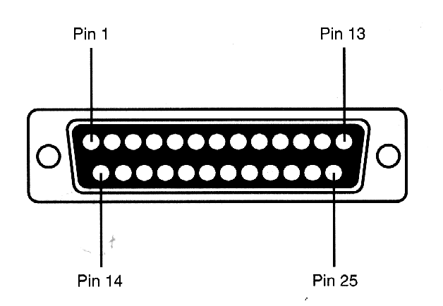
Parallel Port Pins
| Pin No | Name | Direction In/out | Register | Hardware Inverted |
|---|---|---|---|---|
| 1 | nStrobe | In/Out | Control | Yes |
| 2 | Data 0 | Out | Data | |
| 3 | Data 1 | Out | Data | |
| 4 | Data 2 | Out | Data | |
| 5 | Data 3 | Out | Data | |
| 6 | Data 4 | Out | Data | |
| 7 | Data 5 | Out | Data | |
| 8 | Data 6 | Out | Data | |
| 9 | Data 7 | Out | Data | |
| 10 | nAck | In | Status | |
| 11 | Busy | In | Status | Yes |
| 12 | Paper-Out / Paper-End | In | Status | |
| 13 | Select | In | Status | |
| 14 | nAuto-Linefeed | In/Out | Control | Yes |
| 15 | nError / nFault | In | Status | |
| 16 | nInitialize | In/Out | Control | |
| 17 | nSelect-Printer / nSelect-In | In/Out | Control | Yes |
| 18 - 25 | Ground | Gnd |
In the table - when hardware inverted is yes, it means that when you write a 1 to this pin, it will output a 0, and vice versa.
In the past, this was used to connect many peripherals, like you would now use the IO pins of a Raspberry Pi or Arduino. You can learn to connect things to this, and program this port at our Simple Parallel port LED Board article.
- Jan Axelson’s Parallel Port FAQ is somewhat helpful if you are having trouble with this.
- Interfacing to The IBM-PC Parallel Printer Port A nice resource with a few more projects to try.