Using The RCX With Stepper Motors
Introduction
This concept applies not just to the Lego RCX, but should in fact serve any other application where you would like to convert PWM signals to drive stepper motors. It is a bit of a kludge, and you may be better off using a microcontroller with a digital output to send step signals. In some applications, including the Lego RCX, PWM outputs is all you might have free.
Please click any image for an enlarged view.
Recap
First a Recap on Stepper Motors.
A stepper motor is a multiple coil motor(often 4), which moves a very short distance for each step - corresponding with the coil energised.
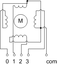
The coils normally have a common connection, and multiple signal connections. It is by signalling those in sequence, that you can move the motor. To reverse the motor, you reverse the sequence - “not the polarity”.
How to do it
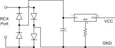
To get outputs from the Lego RCX to do this, you need to bear a few things in mind. Check the voltage requirements of the Stepper, because of the control circuitry, and its requirements - you will need an external power supply (9-12v). This supply will need to be constant. We could not really use a sensor port - as although this may be enough for the control circuits, it would not be able to safely deliver the current required by the coils of the stepper. So we may need to use another output port. The problem being that even at full power- it is still PWM, so you will require a smoothing cap, and a voltage regulator for the control circuits.
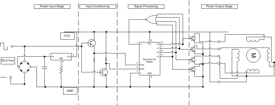
Activating the coils will require a shift register, which allows a roll - or carry operation when shifting, and is reversible - with two clock inputs.
Now the PWM output from the controlling port can be used as a clock pulse for the circuit - but should probably be scaled down to a handle-able voltage of around 5v for the logic inputs - and in such a way that if it is positive it activates one input, and if negative - it activates another. The could be achieved with two transistors - one with a pull-down output, and the other a pull-up output. These outputs then go to the clock lines.

The shift register will need to be initially loaded with a one to shift, and the clear line on it should be held low. This will mean it will require a priming method. The method I will go with is that if all the outputs are 0 - then prime it with a 1. A four input NOR will do this.
The outputs of the shift register should then go to the power transistors, and not directly to the coils.
Bringing all together we have the following diagram. It has no component values.
Conclusions
Looking at the circuit above - it means we will not actually be able to pulse the motor forward once or backward once - given that we really cannot control the actual PWM outputs that finely. I am not sure if we can actually control the rate of them using that circuit either - as changing the power output changes the PWM on to off ratio, and not the clock cycle speed. There are a few single chip products on the market that work in exactly this way from the PWM.
For more accurate control - single stepping, we would probably require a serial stepper controller linked to an Infra Red receiver connected to the RCX.
However - if you are finding you want to do this a lot, then it might be time to consider using a less limited microcontroller.
(paid links)