Interfacing an LED to an RCX Port

Using an LED with the Lego RCX, or the CyberMaster is actually not as difficult as it sounds.
Before building anything, please ensure you (and in the case of younger readers, a parent or guardian) have read Robot Building Safety, and that you have both the correct safety gear, and Robot Building Tools to perform this. All our readers are very strongly advised not to proceed if you cannot perform this safely.
Electronics
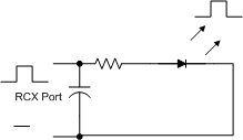
First you need to think through the electronic theory of it. We will assume that we are using one of the output ports on the devices. These output a PWM signal, which will be up to around 9 volts. 9v is somewhat excessive for an LED, but considering the current is fairly low, limiting it further with a resistor should give us safe operation. If we do not want the LED to flicker (this may be imperceptible - but might interfere with IR communications), we should probably have a capacitor to bridge the gaps in the duty cycle of the PWM output.
Now here you can make a design decision. You can either design it so you are using one LED which will light regardless fo which ay it is connected, or so you can have two LED’s so you get a different colour depending on polarity.
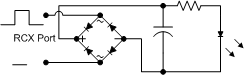
If you went with the first decision, you can build a diode bridge- to rectify the current before it goes into the capacitor. This will then give you the same direction of current into the LED regardless of how it is connected.
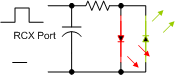
The second is simpler, with one caveat. You could simply build it with the two opposing LED’s in parallel and a capacitor across them to smooth it, but their may be an issue that the capacitor will then be working in a reversed polarity for the other LED.
This is not a problem for smaller disc capacitors, but for larger tantalum and electrolytic - this would be a problem. What we can do to stop this problem, is introduce an additional 2 diodes, and another capacitor.
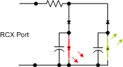
This means that each capacitor is only working in one direction across the LED.
Physical Connection
You can probably fit each of those simple circuits in a single Lego block - I would say a 2 by 2 brick for the 1 LED model, and 2 by 4 for the Two LED models.
The best way to do this would be to take the brick, and drill out the central column - to fit a small PCB inside. Then you drill out one side for the LED. You can then solder the PCB and push it through (LED first). For the connections - you can use one of a few methods:
- Find some thin tin (biscuit tin perhaps), and put this either side of the inside of the brick
- Use a 2x1 electric plate - cut out a matching slot in the brick, solder connecting leads to each of its studs. You then put the PCB in position, and glue this in afterwards.
- Drill out two of the top studs, and replace them with cheese-head screws at the same size (as the studs). You attach your leads to the bottom of these.
If you are doing the first simple circuit - you might be able to FreeForm it. You take the LED, and cut its cables short - to about 5mm. You then take the resistor. Cut one of its leads short, and using pliers, bend the other 90 degrees at around 2 or 3 mm. Then - at around the same place as the other lead of the LED - bend the bent resistor lead another 90 degrees. Then take a disc capacitor, and again using pliers, bend out the two cables at 90. Solder one to the long bent resistor lead and the other to the free LED lead. Connect one power input to the resistor-capacitor junction, and the other to the LED capacitor junction. You should end up with a very small assembly- which will fit nicely into the 2x2 Brick.