Intro
Plugging things into your desktop PC is neat - there is a great feeling of satisfaction when you can program even the simplest of hand made peripherals to light up. This project tutorial will start you with basic interfacing with your computer. Please be a little careful here, as shorting pins on your parallel port could be very bad for your computer.
The Light Emitting Diode (LED) draws very little current when limited by a resistor and some can be lit at low voltages like 0.6v. For a single LED you will not need an external power supply. Without the resistor it may destroy the LED and the port too. We will use a 470 Ohm resistor for this.
An LED is a diode, and under normal conditions will only allows current to pass one way and light it. The two electrodes of the LED are known as the Anode and the Cathode.
A parallel port has up to 12 outputs and 5 inputs. To turn on the LED you set one of these outputs high.
You will need to build an Experimenting Parallel Cable before starting this project.
Required Tools
- A Soldering Iron
- Solder
- Small Clamp or Helping Hands
- Side cutters
- Wire Strippers
- Pliers
- A well lit desk.
- A PC with Parallel Port
- A Multimeter
Experimenting Cable - Parallel breakout
This cable can be used for other experiments, and is just a breakout cable to work with. You can use in a few projects so you don’t have to buy and fit more than one DB25 connector. I recommend using the crimp/press on type of connector, as the soldered type is quite a bore and tricky.
Parts List
- A DB-25 Male ribbon connector (Mouser have these).
- A 26 PIN IDC DIL (Dual in line) female connector
- A 26 Way Ribbon Connector - make it long, you don’t want the project hanging from the back of your computer. Get one with a red cable, or paint the cable on one wire in a colour different from the rest.
Making it
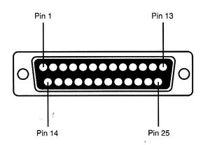
Inspect the DB-25 connector - it should have a tiny (and possibly hard to read) 1 or some notation for pin 1. Line up one end of the ribbon cable with this, push the ribbon through so every wire is sat on a tooth of the connector, then push this down (pliers will help) so the teeth have bitten well into the cable.
At the other end of the ribbon, take the DIL connector, and push the ribbon through that, and then push down hard with pliers too.
Optional testing
Okay - this can be tedious, but is very much worth it before you plug anything into your relatively expensive computer. Using the multimeter, systematically test the pins on the DB25 making sure that none of them are shorting with any neighbours.
Simple LED
Using the cable, we will add a single LED lamp. This will light if there is a positive signal on the connected output pin.
Parts List
- One 470 Ω through hole resistor
- One small through hole LED
- A small length of wire (insulated, but you can use some tape to insulate it) - cut to about 3 cm.
Building the hardware
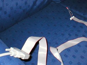
Examine the LED and locate the flat edge. The cable below this is your cathode - the negative side of the LED. Bare the ends of the small length jumper wire to around 5mm. Tin one end of the wire with solder, and the LED’s cathode. Using the solder clamp, or helping hands to hold them together, solder the wire to the cathode.
Solder one side of the resistor to the anode leg of the LED. Plug the resistor end into the DIL socket corresponding to pin 5 on the parallel port, and the other side into pin 18.
Programming the port
The port can be manipulated with many languages. I am using Python as it is pretty easy to get results with. You’ll need a python interpreter and the PyParallel extension - it can be run on any platform.
PyParallel details can be found at https://github.com/pyserial/pyparallel.
Start up python, and type:
import parallelMake a parallel object (my code assumes only 1 port, you will need to read the pyparallel doc to deal with multiple ports). You cna then turn on your LED by flipping the corresponding bit:
    p = parallel.Parallel()
    p.setData(1 << 4)
parallel.Parallel() gets us an interface to the default port, and names it p. p.setData will set the data pins (d0-d7) on the parallel port. Making the correct number is a bit of binary magic. We take the number 1 (the root of all binary numbers), and shifting it left 4 - to set bit 4 of the port. This is a write only port, if you want to store it, you can store the current status yourself.
    p = parallel.Parallel()
    led_on = 1 << 4
    p.setData(led_on)
    print led_on
The light will be on. To turn it off you can set the port to 0.
p.setData(0)To make it blink, you need a timer. The time module can do this:
    import time
    p.setData(led_on)
    time.sleep(1)
    p.setData(0)
This will turn on, then off for a second. Put it into a while loop to blink until you stop it:
    while True:
        p.setData(led_on)
        time.sleep(1)
        p.setData(0)
You need to press Ctrl-C to stop this blinking.


