2020: This kit is no longer available.
The Orionrobots shop now has a new product bundle. The Orion Explorer 1 Wall Avoider kit.
The kit takes the Explorer 1 kit, and adds sensors and a breadboard - making it more expandable and fun. Robots are far more interesting when you add sensors to them!
So you can use this kit to make wall avoiding behaviour - making a robot turn away from any object too close. It uses ultrasonic sensors, which in practice tend to work with hard surfaces better than fabrics or plush surfaces. Things which scatter and diffuse sound will be hard, things that reflect it will work fantastically.
The code possibilities are many, and you can chose to use one sensor at each end, both at the front - and which angle. You can plug them directly into the breadboard, or find ways to stick them to the bumpers of the robot.
Here is a video of me experimenting before making it into this kit:
Orion Explorer 1 Robot Avoiding Walls with distance sensor
First Steps with the kit
The basic avoiding behaviour with two sensors out front is this: drive forwards, read each sensor, and if either is closer than some threshold, then turn away from the closer one, then carry on driving forwards.
Building it
Start with the Explorer 1 construction guide. Attach the breadboard to the robot - you can pull off the backing paper and use the self adhesive strip, or save it for later and just use some sticky tak. Stick it to the top - near the front, in front of the cable hole.
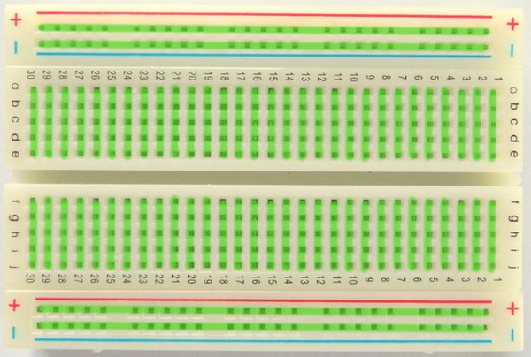
The green lines over this image show the connected pins. Note that the main part of the board has a different orientation from the top and bottom rails. All breadboards (including the two types we have) follow the same basic idea. The sensors will plug into the front end of the pins on the vertical rails.
Then look at the pin labels printed on the back of the sensors. Each will have:
- Gnd - Device ground
- Trig - Trigger a ping
- Echo - Detects the echo response.
- VCC - Device power
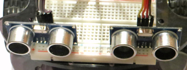
Plug a sensor into the board at each side - with the ultrasonic transducers (big round metal bits) facing forwards.
If you inspect the breadboard - on some versions there are some coloured rails top and bottom - each having one red, and one blue. Convention is that the red one is used for power, and the blue for ground.
Using the male-to-male cables, Wire the VCC from each sensor to the red rail at the back of the breadboard. Remember the pins are connected along the green lines in the diagram above. Then wire the Gnd from each sensor to the blue rail at the back of the board.
For the left sensor:
- Trig -> 11
- Echo -> 12
For the right sensor:
- Trig -> 6
- Echo -> 7
Finally connect a wire from the blue rail to a GND pin on the Uno board, and from the red rail to the IORef (a voltage supply pin) on the Uno board. These connections mean you are ready to program the sensor robot.
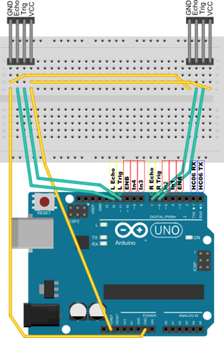
The diagram below shows the connections. The sensors are at the top - with their pins labelled. The connections in blue are those you’ve already made in constructing the robot. Those in green connect the Arduino to the breadboard and those in yellow are on the breadboard only.
Programming the robot - How to make it avoid walls
First lets look at the high level code:
This code can use a turtle library, where high level commands like:
And we can also use a high level sensor library with:
Note that the specific sensor type here is SR04 - so we will be using the SR04 device in our code.
This makes the code above easy to turn into real code. :
Make a new sketch in the Arduino IDE and paste this in. Now how about the two libraries?
In the Arduino IDE - there is a drop down arrow to the right of the typing area - pull this down, and click “New Tab”. We’ll put each of the libraries in its own tab. Name this “TurtleMotors.h”. This will consist of two parts. First the low level Motor type. It will need to store the pins it uses for enable, 1 and 2. With the motor controller in the Explorer, the in1 and in2 pins set the direction, and enable turns it on or off. The speed setting will mean enable is turned on and off very fast, and sets how rapidly it is turned on and off. Maximum speed is the value 255.
On top of this, a high level turtle library can be used to control the motors a bit. It needs to handle two motors turning, and automatically turn off after a time step. Since the automatic and turn off stuff is common - we’ll make a function for it and use it a few times. Put this also in TurtleMotors.h:
The full source for that part is at https://gist.github.com/dannystaple/7586031#file-turtlemotors-h.
Finally we’ll need a distance sensor library. The comments in the code explain its operation. In short it triggers a ping, then times the return pulse, and uses the speed of sound to get the length. Put the following in a new tab called “DistanceSensor.h”:
You should now be able to compile it and send it to your robot. It will do a fairly good job of avoiding walls, but it will be easily confused when it gets caught in a corner.
In a later blog - I will look at ways to avoid the confusion - readers can also ponder this and write their own - let me know how you got on!