Introduction and Background
I’ve started planning on using a pair of Sparkfun Microviews on my PiWars 2018 robot. However, given I have only 2 functioning ones, I felt it was time to revive the other two. These have been sat in demo only state since 2014.
To give some background, the Microview is an Arduino style chip paired up with an OLED display, which I backed as a Kickstarter way back. The original ones arrived, and displayed demos, but couldn’t be flashed. Unfortunately, in the batch I received, they’d been mass flashed with the demo without the bootloader. Sparkfun and the Microview team were very apologetic, and sent a fresh pair. However, they also made it clear the old ones could be kept and revived. I have to respect them for this - and thank them for a great device and a great way to make good their mistakes!
I started with finding a good guide from Make Magazine - How To Fix Your Broken Microview. So how did it go for me?
Getting it Apart
So last night, I used a metal spudger to pry off the glass - this was a little fiddly, but definitely achievable. The next part was soldering on some contacts for the programming pins. Annoyingly - I could not find that nice reel of 28 AWG wire - I’ve not seen it since we moved, which has been a common problem for a while.
So I used some slightly thicker single core bell wire - which was tiny, but is stiff wire, not flexible. This was a really tricky job, and I definitely damaged each of the cases with the soldering iron in a minor way. It was frustrating, the cables kept falling out - and although done, I’m still worried that there is little mechanical strength in their connections.
Preparing the Programmer
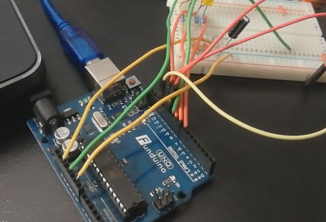
On Sunday I then started wiring up the things I’ll need:
- An Arduino UNO - with the “AVR Programmer” sketch on it.
- A tiny breadboard to make the connections to Microview.
- A Capacitor - 10uF.
- A bunch of hookup wires - M-F for the wires I soldered into the Microview, and M-M breadboard jumpwires for the rest.
My first step was to put the code on the Arduino. That was easy - although I had to comment in the “use old wiring” for it.
I then pre-wired the breadboard, and wired the Arduino connections in.
Where things go wrong
After this, I needed to slot in a Microview, and then connect the final connections - MOSI, MISO and CLK.
The last one went wrong - the clock pin snapped as I added it again, so I’d have to solder them again. This was the innermost connection, behind the other tw.=o. First - I’ll try swapping out the Microview for the other one and flashing that. HHopefully - I won’t encounter the same… And murphy gets ya every time! 2 pins snapped off here. Clearly - the way I’d soldered on doesn’t work. Can I hold wires in place to do it?
Preparing to Flash
Before that - there is an avrdude command I need to prepare. But even for this - I need the env with avrdude in it. Lets create “arduino_env.bat” in my home dir, so it will set up my arduino environment (and allow me to do this again). Since there was a slightly involved command line - I’ve then put that in a “flash_microview.bat” with the file paths and parameters all set up. So I can just run that when ready. Doing this lets me check the command line and takes some of the timing and risk out. Plus it’s often easier to check a command line in my favourite IDE than actually in the shell itself.
In this - I brought up the three variables I’m most likely to change to the top, then substituted them in the command line.
First attempt - failed
Ouch - result is that avrdude didn’t recognise the devices.
    C:\Users\danny\Downloads>avrdude -C "C:\Program Files (x86)\Arduino\hardware\tools\avr\etc\avrdude.conf" -P COM10 -b 19200 -c avrisp -p m328p -v -e -U flash:w:\Users\Danny\Downloads\MicroView_combined_8-19-14.hex -U lock:w:0x0F:m

    avrdude: Version 6.3, compiled on Dec 16 2016 at 13:33:19
            Copyright (c) 2000-2005 Brian Dean, http://www.bdmicro.com/
            Copyright (c) 2007-2014 Joerg Wunsch
    .
    .
    .
    .
    .

    avrdude: AVR device initialized and ready to accept instructions

    Reading | ################################################## | 100% 0.04s

    avrdude: Device signature = 0x000000 (retrying)

    Reading | ################################################## | 100% 0.05s

    avrdude: Device signature = 0x000000 (retrying)

    Reading | ################################################## | 100% 0.05s

    avrdude: Device signature = 0x000000
    avrdude: Yikes!  Invalid device signature.
            Double check connections and try again, or use -F to override
            this check.


    avrdude done.  Thank you.
So I tried again, holding the connection in. This was still not happening. And then during this second attempt… a pad broke off. 😔
I thought “Going to put this to bed for now, and focus on getting the working Microviews into my robot.” This felt like game over, and I was just about ready to quit. And took a tea break…
But wait… Did I miss something?
About to Give up and move on - I notice something had been bothering me- I wasn’t event getting the demo on the Microview. And then after a break (following my earlier pique) I realise - I’d forgotten to connect POWER AND GROUND! Doh! Lets give it another go.
First good sign - I have a display! So it has power. Now try the flashing. A device has been recognised, but nope, not quite - not reading very well.
Back to the Solder Station
This time - I found some fine 28AWG wires - and reused them (still no sign of my blue reel of wire). I trimmed them, stripped them, tinned them and soldered them on. They were multistranded - and the existing setup using dupont cables wasn’t going to work with them. So I used some Wago blocks as a stopgap to connect them.
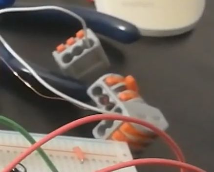
I did this on the one Microview with all it’s pads - so the easier of the two. Then I connected it all back up…
I then made a third attempt.
The flashing worked! First time. And to prove it - I uploaded the cube sketch.
Time to desolder them, and then try the other board…
Fixing the broken pad board
The broken board pad was probably due to the early attempt with bell wire, wiggling and too hot a soldering iron. My iron has a adjustable temperature via a dial, but there is no readout or printed temperature on it. A new iron is in my tool purchase list.
Whatever the cause - I needed some way to get it to work.
My first thought was to get it out of the case - and see if I could solder on the other side of the via - if it was exposed.
This took some doing - I had to cut off some of the plastic retaining clips, then use a vice for gentle but even pressure to do so, which worked a treat.
Unfortunately, after getting it off - I found that the underside of the via really was covered - by a chip. So no help there. I now had to find something tiny enough to put in the via instead.
I found a reel of very tiny copper wire in my lab. I was able to strip the varnish from it and solder it into the via. I then soldered the other wires in, set up the wago connectors - and had to barely breath. One false start - and I had to go back and solder stuff in again - so I cradled it as lightly as I could and brought it over to the programming station with the Arduino.
Keeping very still - I got it to flash the bootloader!
So I yet again uploaded the Cube demo - resulting in the following footage on a bare microview without it’s case:
I desoldered the wires, put it back in it’s enclosure and then replaced the glass.

Conclusion
Success comes with failures first - and much frustration.
First Attempt In Learning
FAIL.
This exercise has definitely increased my confidence in a few areas:
- Soldering tiny vias
- Disassembling what look like sealed screwless products
- Mucking around with the Arduino as a programmer.
And I now have 2 more Microviews for my projects!