Over the last few months, I have been busy modelling parts of a PiWars 2019 robot. I am a reserve team, which means I may not make the main line up, but I still take this seriously enough to make sure I have built a robot for it.
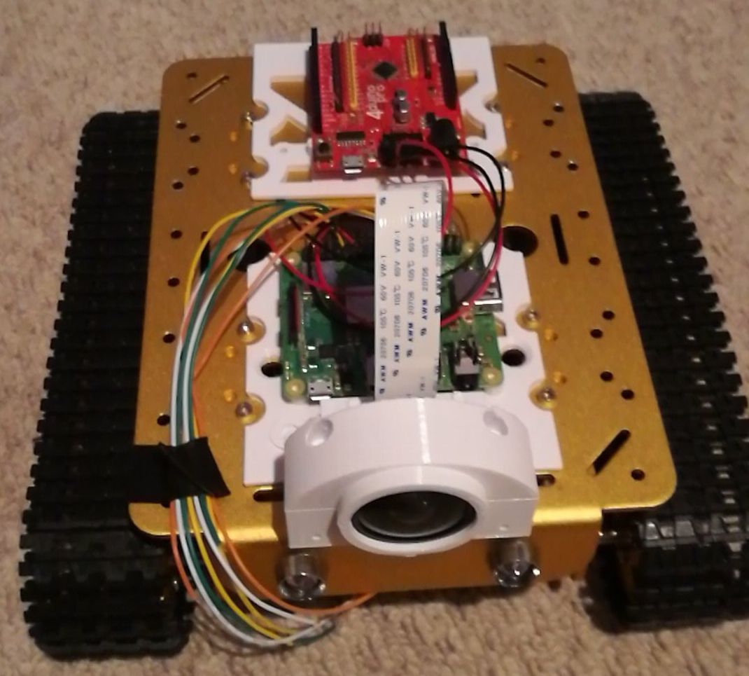
This year I have gone for a CAD modelled and 3D printed system, where my intended goal is robustness. My robot last year suffered many faults in this area, with sensors that dangled off, wiring that shook loose, and best of all, a battery pack that fell out of the back of the robot when it went up a slope severing power from the Pi. Fun, and frustrating. The robot last year was a toy hack, built out of an Amazon excavator toy - probably the subject for another post which I’ve not yet written (I’ll put a link here when I do that). Last year had a couple of 3d printed parts, but I had a printer that barely worked and my experience was limited. This year, I’ve got a load more experience, and a brand new FLashforge printer.
To make the robot more robust, and also include some of the nice options, 3D printed parts seemed the right way to go. I am trying to make them replaceable, which will mean printing spares. I want it to be solid - not rickety at all, and the final stages will be cable routing channels to provide strain relief to all of them. However, that’s getting ahead a bit.

I have a video coming on this, but the chassis I started with was donated by 4Tronix Uk. This had some issues, namely that it was too big for PiWars in it’s default configuration, and that I couldn’t find any CAD drawings.
This lead me to getting my Calipers out, and modelling it. All of it. Now I found an article on hackaday that covered this very well Measuring Parts Badly for Accurate Reverse Engineering - Hackaday which is a great starting point on this. The procedure I took was to model the main chassis outline, dimension this in a Fusion 360 Sketch, then start adding the holes in as subsequent layers. This mean first creating a rough hole or shape for each, then coming back around with Calipers to dimension them. I’ve got a slightly (probably incorrect) method of measuring to the centre of a circle where I’m eyeballing the middle, pointing my calipers there, and rounding to the nearest likely sounding in millimetres. I may have to do the caliper math, where I measure the diameter of the hole, and the distance to one edge, then add half of one to the other for a more accurate layout. However, this has shown to be accurate enough for the 3D prints to work.
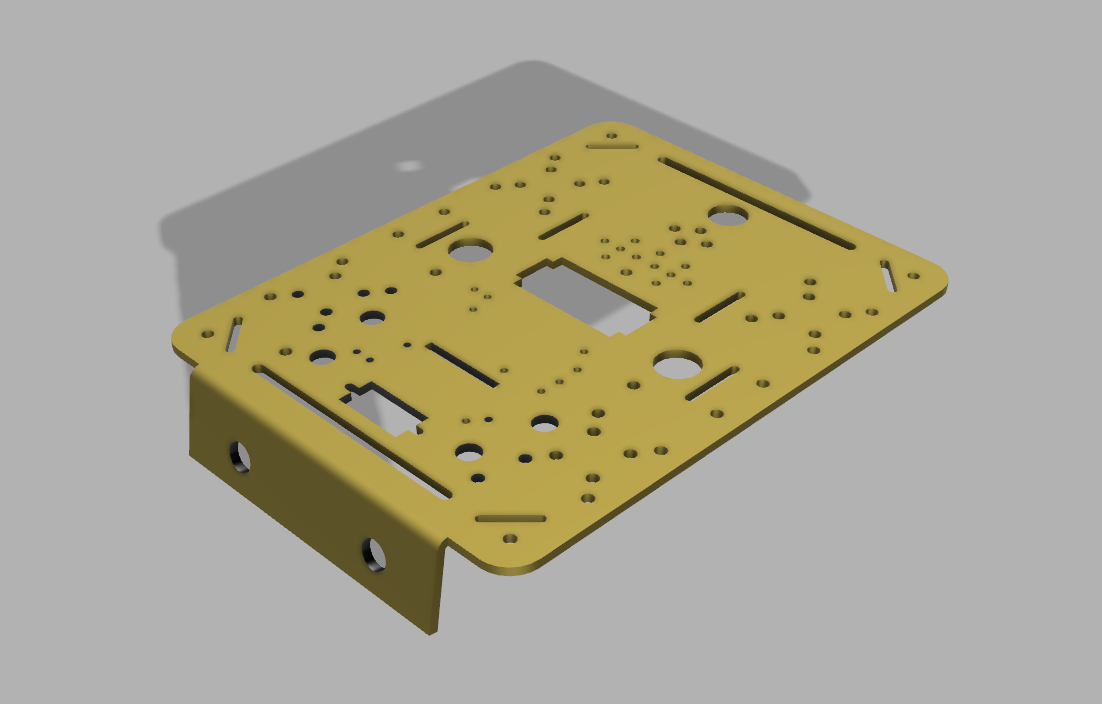
Fusion 360 Model of T200 Main Chassis
I’ve been busy modelling out more parts, and I am not going to try covering it all in one post. So expect more models from the library as I make them available. I will happily accept contributions to improve them.