I’ve finally designed a USB Battery mount for my PiWars 2019 robot. I designed the mount in Fusion 360, and this is the first iteration that I can 3D print. This article contains paid links.
Perhaps to find out why effort has gone into this, it’s worth going back to previous PiWars. Piwars is a robot challenge event where teams build robots around a Raspberry Pi to compete on autonomous and manually driven events.
PiWars 2018
I’ve not posted much yet about my piwars robots, but in last years event, my robot there had a couple of annoying (embarrassing) failure modes related to the batteries and power.
- If the robot went up a steep enough slope, the battery fell out!
- The robot was top heavy because the battery packs were mounted far above the centre of gravity so that the robot would topple backwards.
- The motors and Pi shared a power source, the voltage slump from moving those could reset the pi.
- The power cables were not reliable enough. They came apart turning off the robot at inopportune moments when a little vibration was present.
I resolved to get these problems fixed. Sure, there were code bugs, but I could fix those on the day. These kind of hardware failures were a significant problem and threatened to cause corruption to the SD card or a robot that wouldn’t come back. They were top priorities in my list of things to do better next year. The batteries were based on 2 sets a 4xAA batteries in a series configuration, which I’d tucked into the back of the robot, and held in by a lip of plastic, and later a bit of gaffer tape.
Writing a book
(paid links)
Last year, after Piwars I wrote the book Learn Robotics Programming, and in this I recommended a strategy using two sets of batteries. This meant that power for the Raspberry Pi, logic and sensors came from one battery pack, and power for the motors and LED’s from another.
For this I used a USB power supply (portable phone charger) for the Pi, it’s already a nice regulated 5v, it’s rechargeable from a USB mains adaptor with built-in safety circuits. These are quite easy to use with the Raspberry Pi and make a lot of sense. Very convenient.
For the motors I used a set of AA batteries, recommending Metal Hydride rechargeables over straight Alkaline, merely because they can output more current, but in a pinch, alkaline batteries will do fine. Motors and their controllers tend to be tolerant over a small range of voltages, and the speed differences can be ironed out by using an encoder to detect the speed, a technique covered in the book.
Multiple battery packs like this can be bulky, and there may be smaller solutions using Lithium Polymer batteries, but they come with some trade-offs in safety and protection circuit you’d need to figure out yourself. They also require special chargers - this is OK if you are using them a lot though.
The PiWars 2019 Design
From the outset, I planned the Piwars 2019 robot to follow my book pattern, with separate battery packs for the logic and the motors, although I did toy with the Lithium Ion or Lithium polymer packs, like the racing packs used for RC cars, I decided it would be good to continue in practice what I’d recommended in my book.
Making sure I’d used the two packs would solve problem number 3, the voltage sag issues that I’d experienced when the motors were loaded causing the Raspberry Pi to reset.
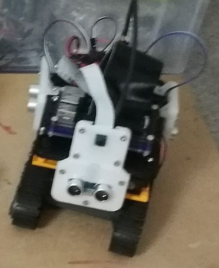
The next problem was where to put them. I needed to avoid issue 1 that the batteries could fall out of the robot. I based my 2019 robot on a T200 metal tank chassis from 4tronix. The flat metal chassis gives a nice divide, anything below that chassis line would be below the centre of gravity.
The battery mounts need to fit around the gearboxes I made for this chassis (a story for another post), leave room for motor cabling and bolt nicely to the frame.
For the AA batteries, Simply making sure there are posts to screw an 8xAA pack would help. It would then be a matter of designing any nearby parts (line sensors are yet to go on) so that it doesn’t make these difficult to change. However, I’ve not yet mounted these, so watch this space for changes.
The USB Battery Pack
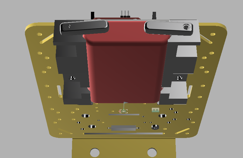
The USB battery pack was more complex and has required more design. I wanted to put it at the back of the robot, where it will use the space above the gearboxes. It’s a curvy design, so I needed guides to hold it. I needed to ensure it would not fall out of the robot again (problem number 1) so it required a retaining system. It also needed to be recharged, so either I could charge it while in the robot, or detach it very quickly.
The space above the gearboxes was limited, so the mounting design had to be relatively low profile. I had a few ideas, and I toyed with them for a couple of weeks.
- Creating a fancy drawer/tray for the battery. I decided this would be difficult to 3D print without it getting stuck.
- Create some cylindrical clips with a big front plate to hold the battery in place. I would 3D print the clips and the curvy part they would lock into. I decided this would be too hard to design and print within tolerances and could be bulky also.
- Encasing it into the robot, and making a breakout board to charge the battery without removing it. I got as far as designing the board for this in KiCAD before I decided this was getting too complicated and was overkill.
None of this seemed right, I was ready to give up on putting them underneath and put them on the top, but then it hit me, I could have curvy guide rails, 3d printed, and a clip with some detents (positions it would happily sit in) to keep the battery in place. Once I had this idea, it took about 3 hours to design it. I needed to account for the bolts holding the side brackets in place, and the top plate, but better yet I could use those to mount the rail.
Fusion 360 (my current 3D cad software) definitely delivered, although I had a few issues with performance. I had modelled the battery a couple of weeks ago when I first started on this problem. I also had most of the robot chassis modelled. I had been able to use that to design the Raspberry Pi mount, and the front Camera/sensor assembly.
The Gearboxes and side brackets were partially modelled, but not in the same Fusion assembly.
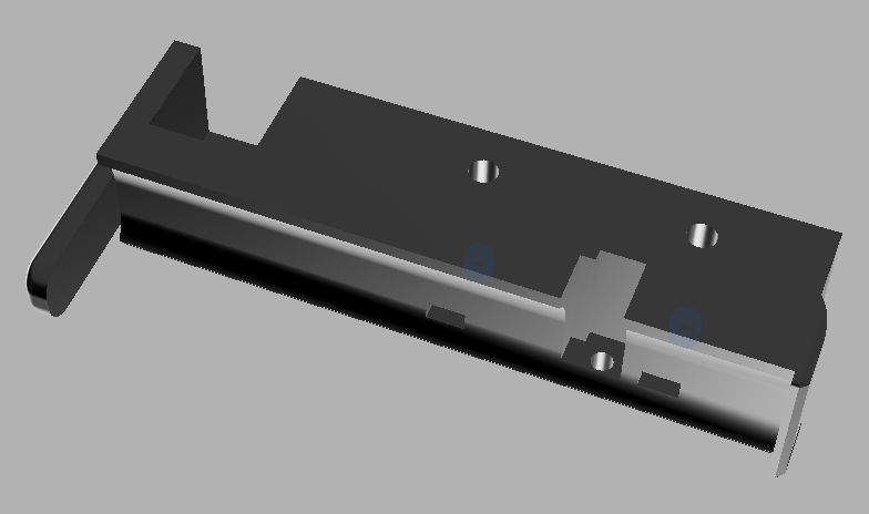
For the rail, I started by placing planes to model the constraints of the clip, in terms of where the gearboxes would be. I used the battery as a guide. I sketched a rectangle, plus some concave curves to fit loosely around the USB battery pack.
Rail Design Mark 1
I was then able to extrude this sketch out to the length of the battery pack. I projected the mounting holes for the other parts from the chassis into a new sketch and used this to cut rectangles around them to get nuts on to them, and holes for the screws to go through. This would let me slide the battery in, but it would keep sliding. So upon the innermost end of the rails, I sketched on the end of the rail, creating a lip that would stop the movement of the battery pack.
I then needed some clips for the outermost end. For this, I created a hole for a screw, going through to one of the rectangles I cut earlier so I could put a nut the other end of it. Beside this screw hole, I use rounded rectangle shallow cuts, which would be the detents - the positions that the clip would be able to rest at.
The clip itself would be a simple rounded rectangle, with a hole at one end. It would also have a tiny protrusion, a little lump, designed to mate with the detent holes. I’m hoping that the PLA is springy enough for this to work, or I’ll find some tiny compression washers to do this job for me.
I used the fusion 360 mirror tool to make the other side, and a bunch of joint connections between the parts to assemble it.
I used chamfers along the bottom corners to try and make it easier to lift from the bed, which only marginally helped.
The first attempt to print it failed, due to a filament issue after the first layer.
Being a little impatient, I used the low quality (draft) print setting, a bit of an experiment, but I’m not relying hugely on precise detail other than the detent.
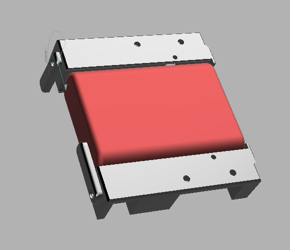
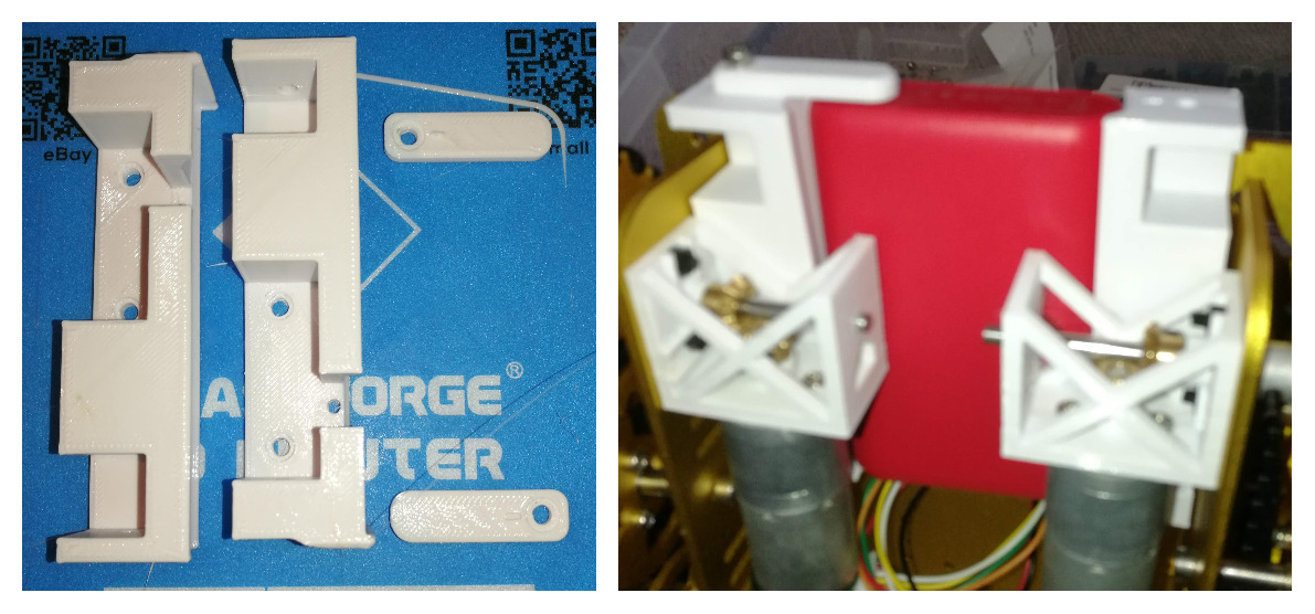
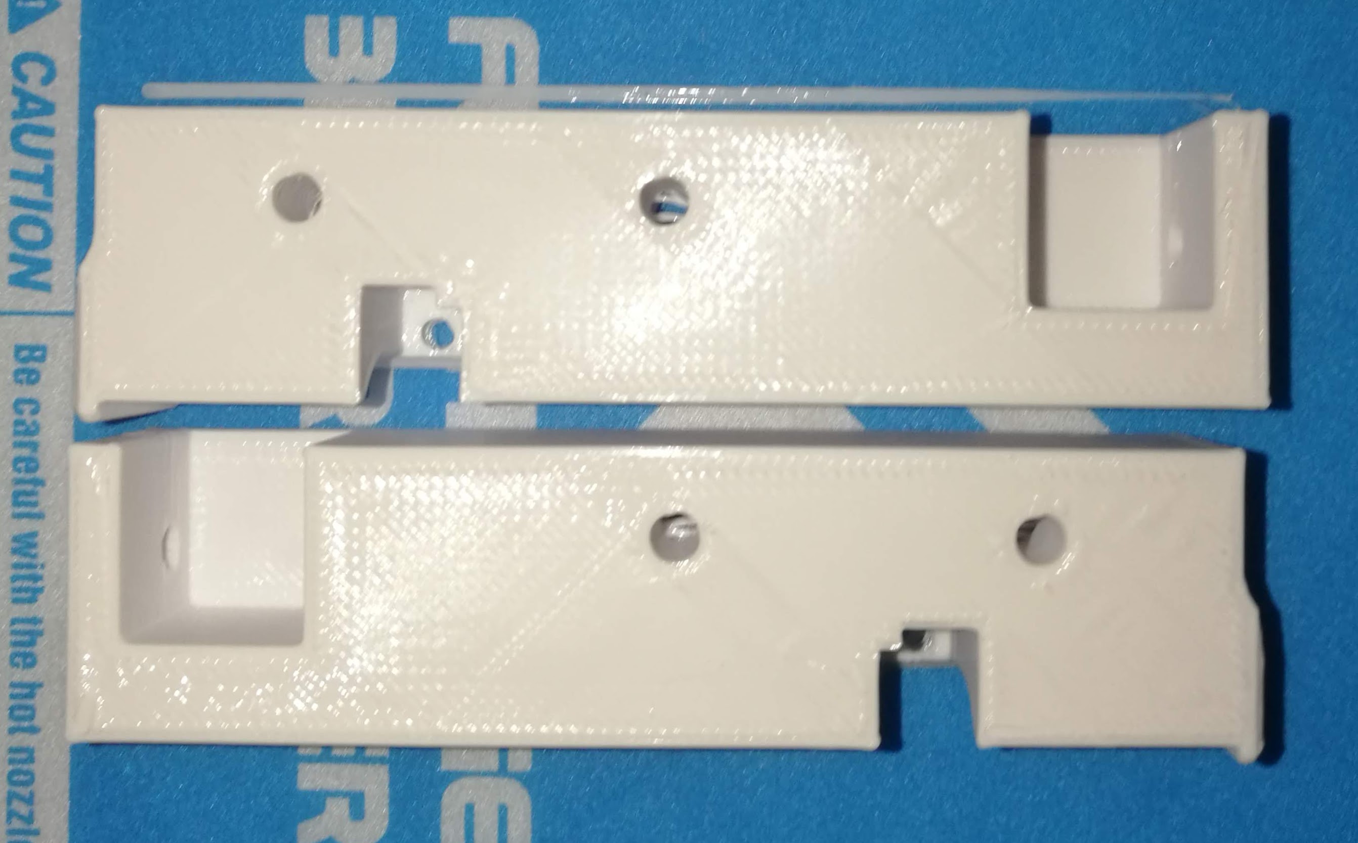
The second print attempt came out beautifully. The battery slides in correctly, and clips fit over it. I am not entirely sure about the springiness and the single detent on each so I may need to add more to that. All of the bolt holes lined up correctly.
There was one slightly significant flaw though, between the battery mounts and the chassis side plates, there was no way to get my fingers in to tighten any nuts.
Mark 2 - Second Design
I have options to consider here:
- Make cut-outs for me to get my fingers in - this will be fiddly, and make the parts frustrating to change out later. It’s by far the easiest option. Perhaps worth making just to move things forward.
- Make the nuts captive, so I don’t have to worry about finger tightening - this is quite a compelling idea. Slightly tricky to get right, but I’ve done it before and made it work.
- An alternative version might be metal inserts. This would be new territory. I’m never afraid to learn new skills, but piwars is imminent and time is running out, perhaps not this time, but consider it on my list of stuff to get the hang of.
I am going start with option 2, falling back to 1 if I run out of time. Option 3 will be shelved for now.
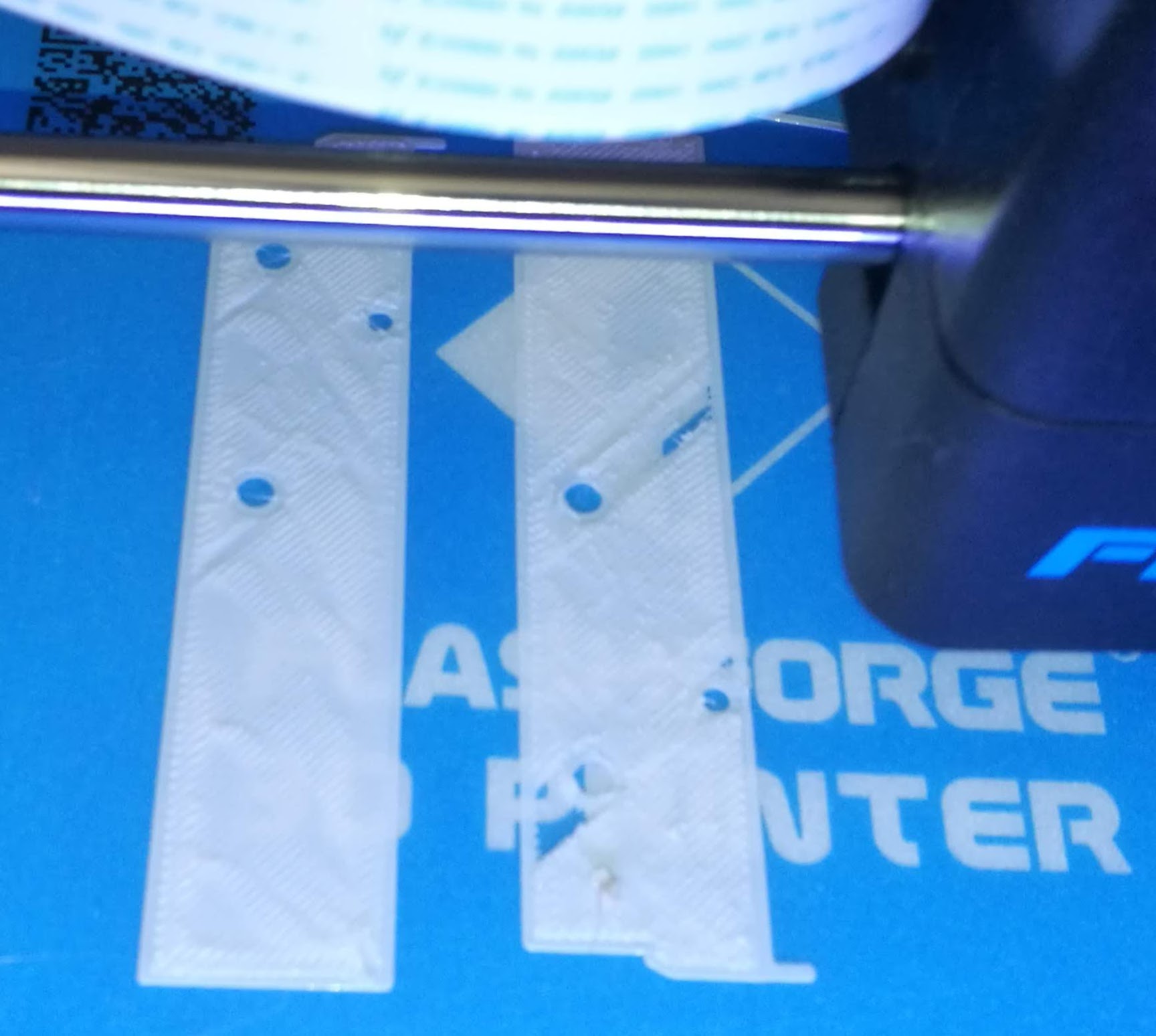
The M3 nuts come out at 5.4mm across the flat parts of the hex. So I’ll create slots for them.
This meant creating sketches for the slots, extruding the main block upwards, and cutting holes through, but finally, I got a printable idea. I had to fiddle a bit with the history to put the joints after the new extrusions. That way I could then move the mirror operation (creating the left-hand side from the right) past the new extrusions.
The first time printing again hit a failure, a small amount of stray filament from the nozzle (I should probably preheat it to relieve any pressure) stuck to the first layers and made a mess of them. Luckily this was only a couple of minutes in, so I was able to try again immediately.
These printed great a second time, but I’d not factored in much in the tolerances for the slots. The nuts would not fit in at all. And I’d printed both sides when perhaps one would do to prove the concept.
5.4 feels like I may have rounded down as I got 5.44 on some. This is the right place for rounding up. 5.8 perhaps works with this and 3d print tolerances. Now I’d used this technique before on a part for my old 3D printer, so going back and checking there, I’d used 5.8 before. Measuring the holes that came out of this print with 5.4, and I’m getting 5.1. I’ll go for 5.9 to give it a tiny bit of leeway, as I remember a bit of fiddling and filing with the 5.8mm holes before. And this time, I’ll print only 1.
Mark 3
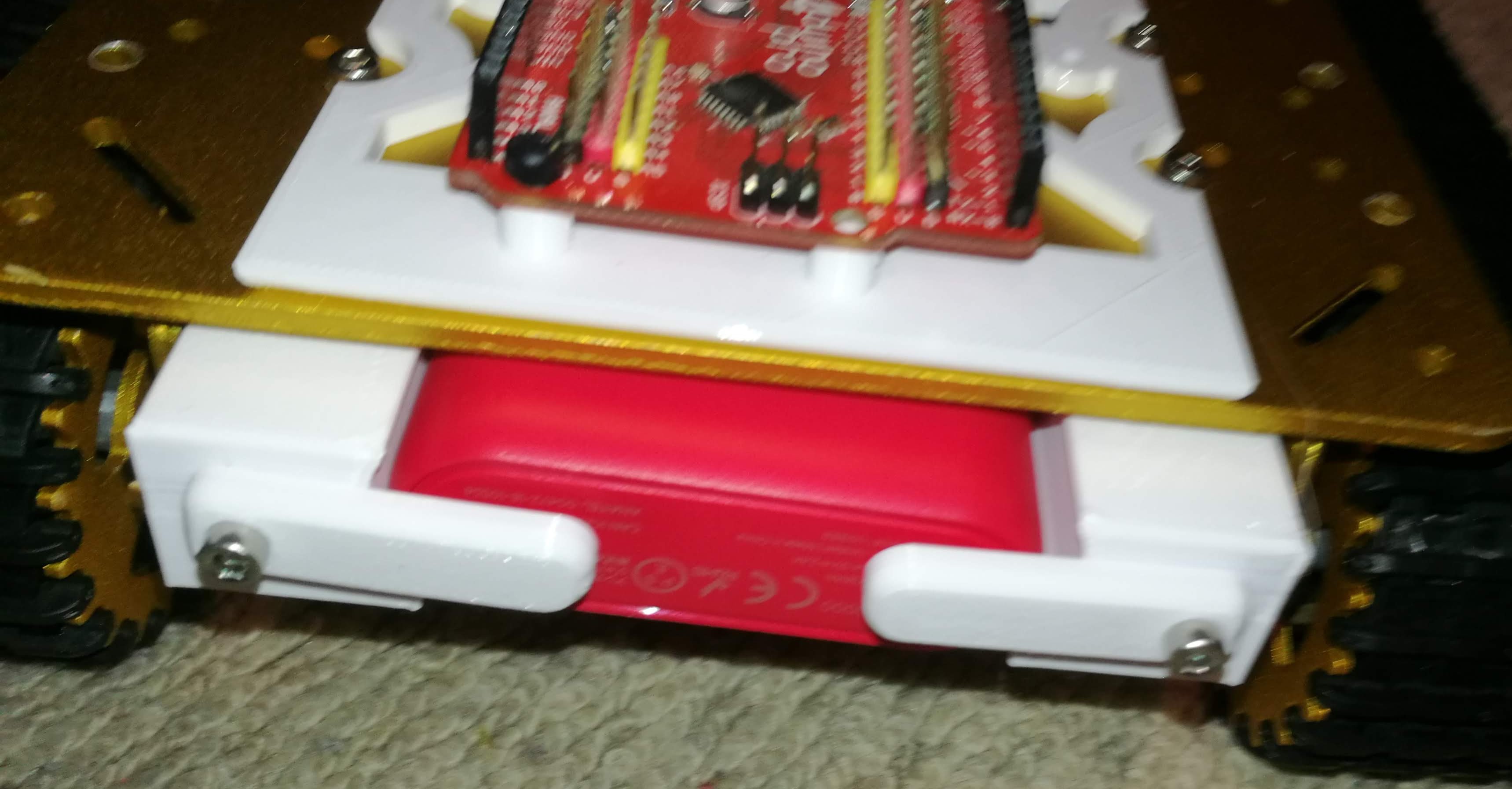
This was merely a matter of adjusting the size of the slots. This time, the model printed first time. The nuts slid correctly into place. The guides are bolted on, although I wasn’t able to get the smaller M2.5 nuts in.
This design fits correctly and the battery is now held firmly. I used M3 split washers (paid link) to provide some springiness to hold the clips on the end tightly, but with some movement. This gives the battery a quick release mechanism for charging. To stop this coming loose, I used a dab of thread locking glue (paid link).
The models:
- The Battery Guide - this is one side, but it can be mirrored. Designed to be bolted under the side plates, with longer M3 bolts, with the M3 nuts pushed into the slots. Print the body, and the clip as separate models.
- The Anker Battery - this is a model for the power bank (paid link).
The next task, for another day, will be the AA batteries.