Piwars Acceptance
Orionrobots has a robot accepted into PiWars 2020. Its name is Bangers & Bash. As a grand overview, I’ve based it on a lunchbox, as a continuation of the MagPi Low-Cost Wheeled Robots series I have been writing.
We’ve decided to give the lunchbox 2 powered wheels and a ball castor at the front. It’s going to have a camera as the primary sensor, with encoders on the wheels (quadrature types) and potentially an IMU (inertial measurement unit). The last item is something I have no experience with and could be interesting.
Like so many PiWars entrants, I’ve been inspired by the talk by Brian Starkey, aka usedbytes at the PiWars Mini-conference to use the camera for more. I’m going to attempt line following, and other challenges with it, instead of more single-purpose sensors. Using the camera for everything requires some interesting code.
The Piwars 2020 theme is Disaster (Zone). However, because our robot is a lunchbox, we (Helena and I) have gone with a food theme. The lunchbox leads to the name “Bangers and Bash.” In terms of styling, Helena plans to make the top of the lunchbox look like sizzling sausages on a barbecue. When we get a functioning NERF attachment, she will decorate it to look like a hot dog.
Helena and I made a video talking through our proposition.
Bangers and Bash part 1 - Piwars 2020 Planning
Parts
Most parts for the robot are ordered, or already in my stock. The lunchbox is a simple Poundland model - nothing special there. I’ll add 3D printed brackets to hold stuff together.
I’m using a Raspberry Pi 3a+ as the controller.
A 4400mAh LiIon battery pack is a departure for me from using dual batteries in both the book robot, and the PiWars 2019 model, or just using an AA set for the 2018 robot. It can deliver more current without problems and should be enough to run motors and logic without dropouts. I’ll test it lots to make sure this works.
For lights (sizzling effect), I have many LED strips in my cupboard. I have both WS2812 and WS2801 types, as well as I2C types. I expect to put a couple of LED strips on top. LED’s can be both for fun displays and a bit of debug/indication.
The motors I’ve chosen are the 50:1 Micro Metal Gear motors, with an extended shaft and optical encoders. Hopefully, 50:1 is the right balance between mechanical advantage and speed. These have a stall current of 770mA each. I’ll use the Pimoroni adaptors to put Lego wheels on the end of these, giving me plenty of tyre choices. The ball caster is a steel bearing castor.
Motor Controllers
The robot needs a motor controller, with the least effort probably being a Raspberry Pi hat. There are a couple of options for this.
I expect to use IO to drive some LED’s (SPI, I2C or 2 general purpose IO depending on the type of strip), and to read the encoder (3.3v) output from the motors too (4 input pins). The choice of the motor controller should work with my choice of battery somehow too. Because an IMU is needed, then easy access to the I2C pins would be good. I may also have a couple of servo motors for attachments.
For power, I intend to use a DFRobot LiPo boost module. The LiPo boost module has charging and power handling for the LiIon batteries and was sitting in my cupboard for a while. I’m not sure how I feel about the motors sharing the actual power rail for the Pi, but it could work. The DFRobot module can handle 2.5a which may be a bit low for the motors and the pi.
I have quite a few motor controller options, based on what I already have in stock:
-
The Pimoroni Explorer Hat Pro brings out the I2C pins, and 5v tolerant pins for connecting things like the motor encoders too. It uses a breadboard for connections, which have a habit of coming loose at inopportune moments. I may put some soldered connections and JST type connectors in there once the wiring is finalised. The spec for this hat is 200ma per motor channel, enough for the motors running, but not up to much when stalled. I’m not sure how it will cope on slopes or pushing, which will need some testing. The Explorer Hat doesn’t have a slot for the camera cable which could be an issue. The capacitive touch has no function here.
-
The Adafruit Crickit Hat For Raspberry Pi has more of the connections brought out in a way that wouldn’t need a breadboard and uses screw terminal block connectors for the motors. It has many functions that are wasted on this robot, like the capacitive touch. It still needs the voltage boost module and has 1 amp per motor channel. This controller makes sense on a robot with many input/output parts, like my 2018 piwars robot. Not sure I’d use the speaker in this. I’ll need to solder a different header on for I2c connections when I need it. Servo motor connectors are there.
-
The Red Robotics Redboard - this also feels like it’s best functions might be wasted on a robot where the camera is its primary input. I’d need bigger batteries, or series to get the 7-24v needed for this too. It won’t have any issues driving the motors (6 amps!) and powering the Pi (3A supply). The i2c ports and servos are easy to use. But in truth, I’d instead put this bad boy on a bigger robot, like one of the tank models with large motors. This robot does only have teeny motors.
-
I’ve also looked at the option of a Pair of I2C connected Drv8833 boards from Pimoroni that don’t waste any function. I’d need a wiring board for them plus any other parts like lights, encoders and IMU. While fun, the wiring board could make for a bit of mess, and more connections means more failure points.
-
An option that I’ve used before is the PiConZero. One way I could do this is to cannibalise a PiConZero off one of my older robots, with designs on re-spinning it using the RedBoard. The PiConZero can either share 5v from the DFRobot boost module or get a separate power feed from the battery. There’s space for the camera cable because it’s a smaller size. The motor channels can output 1.5a each. However, it also doesn’t expose the I2C pins.
-
SB Components motor shield - this is a straightforward Raspberry Pi hat, but the 6-12v motor supply makes it need more batteries than other options, and compared with the Red Board, it’s a little too basic.
-
I have some simple drv8833, L293 and L298 things I could use too, but that comes with needing to consider soldering up a wiring board to keep things tidy. Also, nothing is more straightforward to mount than a hat on the Raspberry Pi.
For now, I’ll start with the Explorer Hat, and keep the RedBoard as a next potential option if I need it.
Drawings
I’ve then been using Fusion 360 to draw the robot. It’s a bit more complicated than back-of-an-envelope sketches, but essential when I’ll be 3d printing brackets for things inside the robot. I can use it to work out where I need to make holes in the lunchbox, and 3d print some simple studies to check what ideas work.
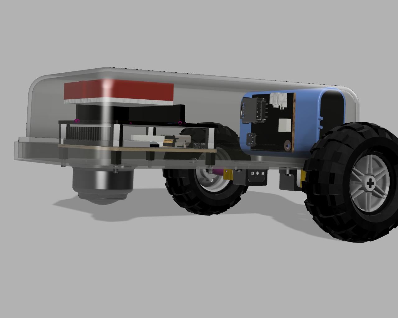
I haven’t got anything for the camera in yet, along with mounting the battery or the top section. There is an odd glitch with the breadboard floating off the Explorer Hat that I’ll figure out, but the battery mounting comes first.
For that, I’m going to do a little study in bendy 3d printing with PLA, so I can make clips to hold the battery in, releasable with a finger on a catch. Expect my next post to cover that.