Background
The Raspberry Pi Pico robot shown in my soon to be released book “Robotics at Home with Raspberry Pi Pico” runs the sophisticated Monte Carlo Localisation simulation. This can produce a lot of data very quickly.
There’s a component to visualise this data with matplotlib on a PC. However, it has one flaw, the Bluetooth BLE connection can only send a small amount of data, so only a subset is sent.
Linked with this is the amount of memory aboard Raspberry Pi Pico.
Idea
I have come up with the idea of temporarily linking a Raspberry Pi Zero W to a Raspberry Pi Pico.
Could I make this algorithm even better, using the Raspberry Pi as an aid to improving it?
This was I get to use a Zero W to visualise data from Pico, over wi-fi, with the sophisticated visualisation work going on in the Zero W.
Depending on what part of the algorithm I am refining, I may even delegate parts to the Raspberry Pi. There I can add lots more instrumentation to visualise these parts, and then migrate that code back to Pico code.
Why Now?
The book writing is completed. The book will be published in 10 days. Why would I make this enhancement for further debugging now?
While writing this part of the book, I found that I had to learn a lot about Monte Carlo localisation, and quickly. I made multiple attempts to write that ambitious chapter, fitting said algorithm on a smaller microcontroller architecture.
The Monte Carlo localisation algorithm currently shipping with the book works, but can take a while to find a location, and may then lose the lock on that again. It also has a habit of locking onto another location, a local maxima, which seems probably based on sensors and the symmetry of the arena, but is wrong. It will drive around persisting guesses in that location, and then scatter the guesses when it hits the cutout.
While this was good enough for the print, it wasn’t perfect. There were publishing deadlines to consider, and I had definitely pushed my luck with those!
So there was room for improvement, and I know with more time I can make that algorithm better. There are some changes that I know improve it, but made the chapter too long, which I can go into here on the blog. There are also refinements or issues I am yet to understand.
I want to be able to give the readers the best experience of this, and deepen my own understanding even further as I find this area of robotics fascinating.
Use cases
Examples of delegated code
The memory constraints on the Pico means the data per pose is very limited. Tagging each pose with some kind of ID would mean I might be able to track how they move. I would be able to see which ones made it through to resampling, and how many “children” poses they spawn, and I would also be able to see how those individual poses were moved by the movement model. At what point do they change enough that they should be considered different children? This would require delegating most of the model, leaving only collision detection and sensor reading on the Pico.
Another thing would be to increase the population size. The memory constraints on the Pico keep a very limited population size. Temporarily relocating the code to a Raspberry Pi means that I may be able to scale that population 10 times, and see how that affects the local maxima problem. Would the algorithm keep, and therefore resample the right location more often with a bigger population?
One really interesting idea would be to run a simulation on the Raspberry Pi, from the same sensor data, shadowing the one on Raspberry Pi Pico, and visualising their respective results together. Do they start to diverge? And where?
Examples of visualisations
The existing scatter plot visualisations would still make sense, but instead of resampling a smaller set to be sent, Raspberry Pi could visualise the whole population. This would make it easier to visualise what is happening, and what stragglers look like.
We can also add visualisations of sensor data. There’s already an instrumented version of the algorithm in the Github repository that shows likely sensor readings as two yellow dots for a first pose in the list of poses. Raspberry Pi visualisation could also show sensor data either as numbers, or other displays around the main scatter plot.
I also hint that the IMU could be brought into play to improve the algorithm. This would make it easier to integrate.
Logging and replaying data
Raspberry Pi could also record the unfolding simulation as logger data so it could be replayed, either the sensor data replayed through an algorithm or the output data replayed through a visualisation.
This will allow the model, or visualisations to be tweaked without having to set up the full robot arena every time. This is an exciting path to enhancing the model.
Does that mean the whole thing is moving to the Raspberry Pi?
No, although a Raspberry Pi Zero W (or other model with wi-fi) will be used for extra visualisation and improvements, the plan is still to migrate any fixes and learnings right back into the CircuitPython code running on the Raspberry Pi Pico.
Overall plan
Here is how I plan to make this happen:
- Create a simple mount for the Raspberry Pi
- Agreeing a communication protocol between the Pico and the Raspberry Pi Zero W
- Powering the Raspberry Pi Zero W
- Wiring the Raspberry Pi Zero W
- Software architecture between the components
- Visualisation layer on the Raspberry Pi Zero W
- Data logging on the Raspberry Pi Zero W
- Shadow simulation running on the Raspberry Pi Zero W
- Tagging poses and their descendants
I’ve already decided I’ll use Python on the Raspberry Pi for this, with Matplotlib. I’ll use a simple flask serve to serve up visualisation data similar to those used in my “Learn Robotics Programming” books.
Mounting plan
It was tempting to mount this as another shelf above the IMU and Bluetooth BLE module. However, my concern is this would place more weight on the castor ball and make the robot dig into carpet causing more friction. It might also make it tip.
Another idea would be to mount it above the breadboard, using something 3D printed to stand the Raspberry Pi Zero W off from the breadboard, leaving space for the breadboard wiring. This could be a part that slides around the four corners of the breadboard so it will be held above the board.
It would then have a shelf above for mounting the Zero W, such that the GPIO pins face down for wiring, and that the micro SD is easy to get to.
The part might want to hinge somewhere, so I can change wiring, without pulling the Raspberry Pi of entirely, however, this might be an unnecessary embellishment.
I would create something in FreeCAD, 3D print it and test that.
Communication protocol
I will not be using Bluetooth BLE between Pico and Raspberry Pi, because the speed of the UART is one of the motivations for doing this. I will also not be using UART.
There are already many sensors using the I2C bus, I would not want to introduce contention by using this.
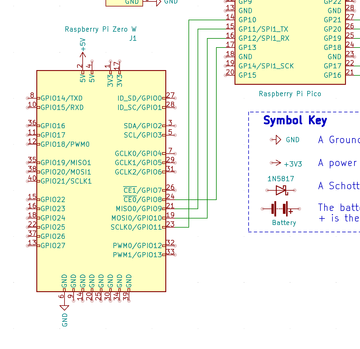
The SPI1 bus pins are free on the book Raspberry Pi Pico, although they do clash with the pins used for the Bluefruit BLE UART, it is reasonable to disconnect that module for this. These are pins GP10 - clock (ScK), GP11 - transmit (TX), GP12 - receive (RX) and GP13 - Chip select (CS) on the Raspberry Pi Pico.
I should check data on using Raspberry Pi SPI, but wiring and in Python.
We can use the Raspberry Pi SPI0 port, which is on pins GPIO 10 - TX, GPIO 9 - RX, GPIO 11 - SCLK, and GPIO 8 - CS. Arguably, we probably don’t need chip select as we plan to make this connection single chip to chip.
SPI will mean we can send full double direction data, or duplex, between the pico and the Pi Zero W.
Powering Raspberry Pi Zero W
Disconnecting the BLE moves us nicely to power considerations. I don’t want to have this tethered, I want it to remain mobile.
I expect that the existing UBEC will be able to power Raspberry Pi Zero W, even with wi-fi running, but that I’ll need to disconnect the Bluefruit BLE module, by far the largest power usage device on the board.
I can then connect 5V and ground power lines from Pico to Raspberry Pi Zero W.
I went to RasPi.TV | how much power to Pi Zero w use? to get some numbers for this. The relevant measurements are a Zero W which has wi-fi connected. The worst use case was 230 mA. A [Toms Hardware Guide](Raspberry Pi Zero 2 W Review) suggests that under stress the Raspberry Pi Zero W consumes about 370 mA.
These figures should be fine for running from the UBEC. Although I am sure a fresh set of batteries is a good idea.
Wiring the Raspberry Pi Zero W
With the above considerations, the wiring seems pretty clear now.
We need 5V power, from the VSys pin of the Raspberry Pi Pico to the Raspberry Pi.
Ground can come from any ground rail on the breadboard. We then need the SPI pins for Clock, TX, RX to the Raspberry Pi Zero W. We could add chip select, although we are not really going to do much with that.
Continuing
Throughout the next few days, I’ll be fleshing out the other parts of this plan in follow up posts.
Links
I used Gadgetoid’s awesome Raspberry Pi Pinouts for checking SPI pins.