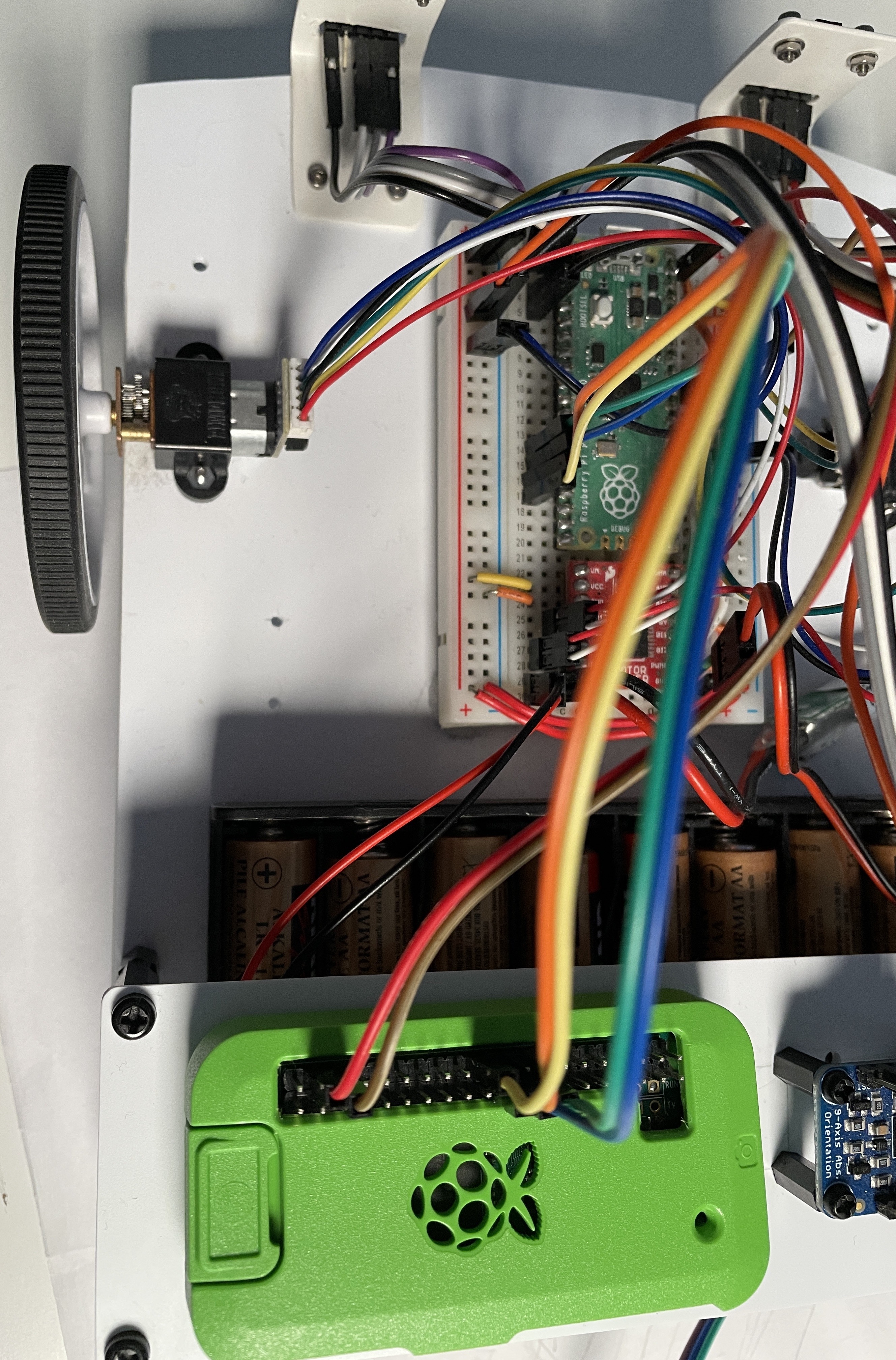
Today is Pi day. As in the number 3.141592, and also the Raspberry Pi.
As part of my work on Robotics at Home with Raspberry Pi Pico, I’ve been working on a robot that uses a Raspberry Pi Pico as its brain. This is a great way to learn about robotics, and also to learn about the Raspberry Pi Pico.

I’ve decided, for various reasons, to retrofit it with a Raspberry Pi Zero W for WiFi debugging, and running code to assist improving the code ont the robot.
Robotics at Home
My book, Robotics at Home With Raspberry Pi Pico drops in 3 days! On the 17th March, you’ll be able to buy this book that has a journey from beginner through to building a floor roving robot with multiple sensors, interesting algorithms and explore the features of the Raspberry Pi Pico. It’s book intended for anyone who wants to learn about robotics, and also for anyone who wants to learn about the Raspberry Pi Pico. I’ve written it from my belief that anyone can build a robot in their home, or in their workshop if they have one.
Retrofitting the Raspberry Pi Zero W
In my last post on this, Using a Raspberry Pi to inspect code on Raspberry Pi Pico I drew plans to add this to the robot. I started today with having located the Pi Zero W, flashing Raspberry Pi OS on an SD card and simplifying my plans.
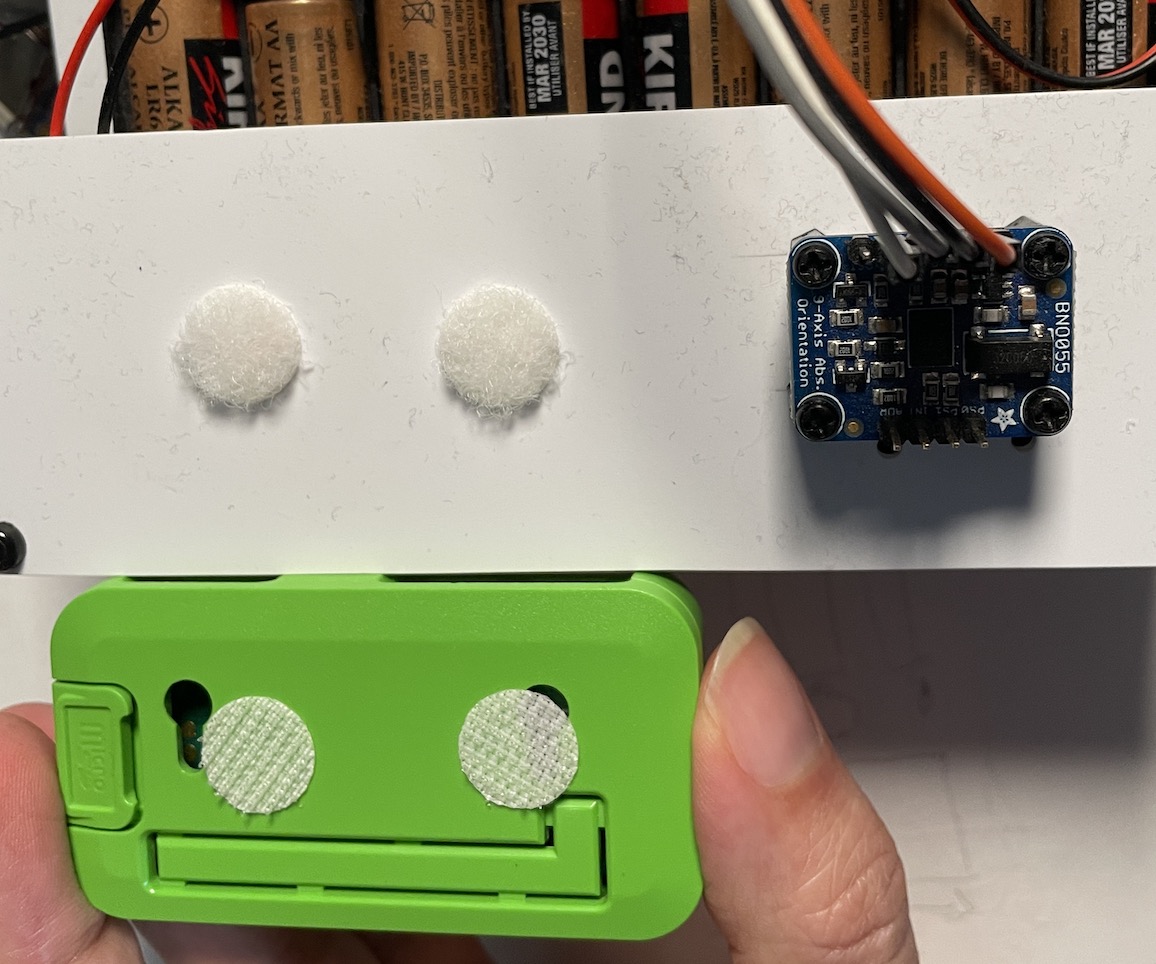
My original plan for mounting was a 3D printed mount. I still plan that, but since I want to get this working quickly, I’m going to use a simple Pi Zero case and stick velcro dots on it, to match the other parts on the sensor shelf.

Powering the Raspberry Pi
My initial plan was to power it from the 5V ish supply. This is a 5v output of a UBEC with a Schottky diode to prevent USB voltage back-powering it. The Raspberry Pi Zero didn’t like this, it was at about 4.5 to 4.6v, and the Pi wants about 4.75v or higher.
This is an easy fix, as I just need to wire things so that the Raspberry Pi is before the Schottky diode instead. I had to change the wiring a tiny bit on the breadboard to accommodate it.
Hopefully, I was powering both. The light was now on the Raspberry Pi Zero W, but it was not on my network. I’d set up the SD image so it was able to reach my home network.
My usual MO for such a thing is to run it headless, and SSH into it. Once all up and running, the next thing was to get them to talk to each other via SPI.
Setting up Raspberry Pi Software
The Raspberry Pi already has Python 3.9.2 installed, so I didn’t need to do anything there. In addition to the Raspberry Pi OS, I also installed the following software:
- sudo apt-get install -y python3-pip
Then the following python requirements (which took a while):
- pip3 install Adafruit-Blinka
- pip3 install numpy
I may add more later, but this should get us ready to test some simple communications. I was trying Blinka so I could migrate some code between the Raspberry Pi and the Raspberry Pi Pico.
We then need to enable SPI on the Raspberry Pi.
- sudo raspi-config
Then go to Interfacing Options, and enable SPI.
We can make the initial test by running the following code on the Raspberry Pi:
import board
import digitalio
import busio

spi = busio.SPI(board.SCK, MOSI=board.MOSI, MISO=board.MISO)
buffer = bytearray(4)
while True:
    spi.readinto(buffer)
    print(buffer)
I put this in test_spi.py, and rsync’d it over to the Raspberry Pi. Then ran it, to wait for input. The first time around, I had to remember the raspi-config step. The second time, I immediately started receiving \xff\xff\xff\xff - not what I expected, but it was a start.
Testing the Raspberry Pi Pico
For this I started up Thonny - a great Python IDE for the Raspberry Pi Pico and a REPL running there. I then ran the following code (in code.py):
import board
import busio
while spi.try_lock():
    pass

try:
    spi = busio.SPI(board.GP10, MOSI=board.GP11, MISO=board.GP12)
    buffer = b"Hello, world!\n"
    spi.write(buffer)
finally:
    spi.unlock()
The finally unlock is so I don’t need to reset the Pico if the code fails. This code ran. The difference now on the Pi is that I’m seeing zero’s.
Either we are using the wrong pins, or they are on different frequencies. Printing the frequencies will quickly eliminate the latter.
On both, we can add:
print(spi.frequency)On the Raspberry Pi, this was 100000, and on the Pico is was 250000. That won’t help.
On the Pico code, after we lock, lets set this.
spi.configure(baudrate=100000)This sets it to 122070. Can we configure the Pi to match?
spi.configure(baudrate=122070)Ahh - this shows something new on the Pi:
Traceback (most recent call last):
  File "/home/danny/test_spi.py", line 6, in <module>
    spi.configure(baudrate=122070)
  File "/home/danny/.local/lib/python3.9/site-packages/busio.py", line 367, in configure
    raise RuntimeError("First call try_lock()")
RuntimeError: First call try_lock()
The Blinka docs didn’t suggest we needed that (or I’m looking at the wrong docs). Let’s make it much more like the Pico:
import board
import busio

spi = busio.SPI(board.SCK, MOSI=board.MOSI, MISO=board.MISO)
while spi.try_lock():
    pass

try:
    spi.configure(baudrate=122070)
    print(spi.frequency)
    # buffer = bytearray(4)
    # while True:
    #     spi.readinto(buffer)
    #     print(buffer)
finally:
    spi.unlock()
I’ve commented out printing the buffer, just so we can sort out the baudrate matching first. This works. Let’s try getting it to print output again.
It is still zeroes. I think the issue here is that I’ve slightly naively set both devices as controlling the clock. The Pico should be controlling the clock.
This is when i found out that the CircuitPython libraries, and therefore Blinka, doesn’t support working as a secondary. Luckily, it’s the Raspberry Pi side I wanted to make secondary, so I can see if there’s another suitable library.
Other libraries
For each library, the question will be, can they play the role of secondary? Failing that, will I need to bit-bang something like it?
Looking at it - bit banging on the Raspberry Pi in python is likely doomed. The library spidev seems oriented towards the Raspberry Pi being the main, and the other device being the secondary. I’m not sure if it can be used the other way around. This may even be a hardware restriction on the Raspberry Pi.
Other Plans
So I now need a plan B.
The Pico won’t act as an SPI secondary in circuitpython, but I could bitbang something with Pio, if I kept it slow. However, the whole idea was to go a bit faster than that. UART is not going to be reliable enough to go faster.
I could go back to trying I2C and see how fast that can go. This would mean setting the Pico as an I2C secondary and the Pi as a primary.