When building a robot, it is important to position sensors where they will be useful in the algorithms running on the robot. Getting it wrong can lead to amusing and odd results.
In this post, I will take a case study of a wall following robot using a PID algorithm, much like that used in my book Robotics At Home With Raspberry Pi Pico.
Case Study - Wall following with PID control
This robot has a distance sensor facing out from a side pointing at a wall. The code was Micropython written by a robotics student of mine based on a Proportional control. The basic idea is this:
distance = sensor.read_distance()
error = distance - desired_distance
correction = error * constant
set_motors(speed + correction, speed - correction)
If you are not familiar with proportional control, it is a way of controlling a robot by measuring the error between the desired state and the actual state. The error is then multiplied by a constant, so the larger the error, the larger the correction will be. By adding the correction to one motor, and subtracting from the other, the robot would turn to try and reduce the error.
However, what this robot did was steer the opposite way, and a part of the loop for line detection stopped the robot as it crossed a line. The student was confused as to why the robot was steering the wrong way.
Let’s look at the positioning of the sensor, the wall and the robot wheels.
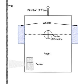
In the image above there is a wall to the left of a robot. On the robot is shown the direction of travel - the direction it is driving. In the bottom left of the robot is a distance sensor pointed at the wall.
The key thing here is where the Center of Rotation is. Note that this will sit somewhere along the axes of the wheels. Lets see how this will affect the PID algorithm.
The Problem
Let’s start with distance sensor being too close to the wall. The sensor will detect a distance less than the expected set point, so the error would cause the robot to turn to the right to move away from the wall, as the picture shows below.
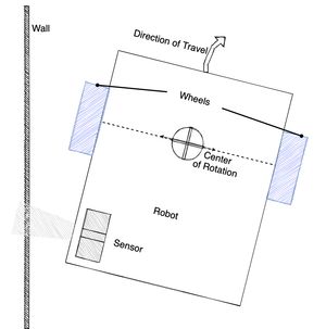
However, as the robot turns away, the sensor, behind the Center of Rotation, will be moved closer to the wall by the turn. This will cause the PID to react further.
The key issue here is that the way the sensor moves does not correspond with the direction of travel during the turn.
Correcting this
There are two ways to correct this. Either the robot can be redesigned so that the sensor is in front of the Center of Rotation, or the direction of travel needs to be reversed, with the robot driving backwards to match the sensor position.
The following diagram shows the robot with the sensor in front of the Center of Rotation.
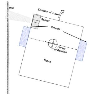
In this image, because the sensor is in front of the Center of Rotation, when the PID rotates the robot away from the wall to make the correction, the sensor reading will be further away too, making it consistent with the direction of travel.
Conclusion
When using sensors to correct the direction a robot is travelling, like wall following, line following or similar, it is important to consider the position of the sensor relative where the rotation centre will end up. If the sensor is behind the Center of Rotation, the direction of travel will be opposite to the direction of the sensor correction.
If you want to build robots to experiment with sensor positions as shown in this article, my book Robotics At Home With Raspberry Pi Pico will show you how to build a robot with a distance sensor for wall following, and how to program it in CircuitPython.