We had only some ideas for lift and grab, but nothing concrete. We had some concept sketches on what we’d like to do. Over the weekend, between the sessions with the whole team, Danny did what he could as we were running out of time for this.
We are able to build on a few things that the robot now has including the attachment plate system, the camera placing, PS4 controller support and the servo motor support. We can use the same LKY61 servos (MG90S clones) that we used for the turret.
Danny started by printing a barrel from the Pi Wars Eco Disaster STL. That way, we could feel it, start thinking about dimensions of it.
Prior Lego grab and lift experiment
Emma had participated last year in the WRO using Lego Spike. A Grab and Lift mechanism was key to making that work, and we’d prototyped a bunch in Lego. one was sitting in the storage area for Big-Ole-Yellow as a possible inspiration for what we’d do next.
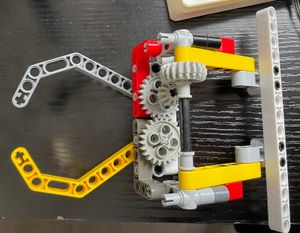
This was based on a single motor as the number of motor connections was restricted. We don’t have such a restriction in Pi Wars, but it was a good starting point.
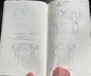
Concept sketches
We already had the attachment plate concept, and knew we’d need an arm reaching down in a way that wouldn’t cover the camera when lifted or lowered. This would be tricky to start in CAD, so some concepts and prototyping were needed.
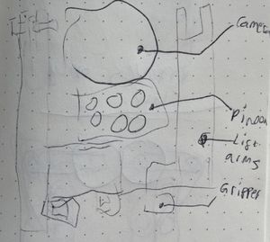
The arms would need to reach from the attachment plate, then down low enough for the gripper. The gripper mechanism, whatever that will be, needs to not cover the camera.
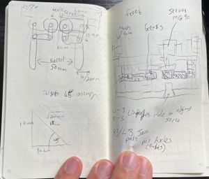
We’d want it to grab the barrel somehow, so a quick concept sketch of that was next:
This top down view shows some kind of geared grabber gripping a barrel. All a bit too rough yet to make much of it. However, this was enough to make the upper arm in FreeCAD. So Danny went ahead and designed this part.
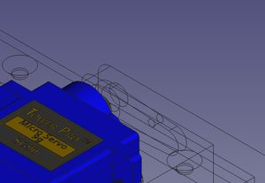
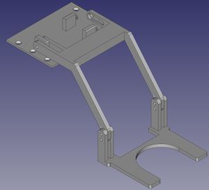
FreeCAD upper arm section
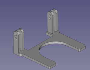
Danny built the upper arm section and the attaching plate for this in FreeCAD.
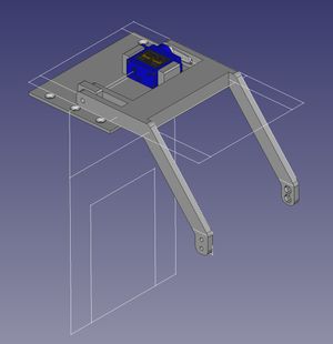
This shows the servo in place, with a servo horn and was all 3D printable. There some top and front master sketches to account for how far forward and down it would need to reach to clear things.
Some detailed views:
This shows the servo horn fitting in the arm. On the first printing, this had to be adjust and reprinted, as measurements of radius (using a radius gauge) had been added as diameters! However, with tweaks it worked.
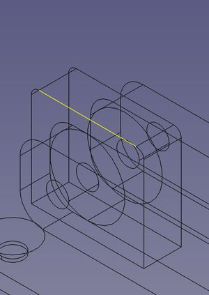
The other side has a bearing in a stand, this has it’s axle at the same place as the servo motor shaft.
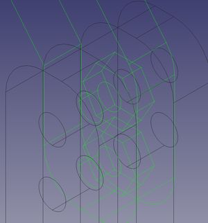
This wireframe view is at the end of the lift arm, showing how some nuts will be held captive between this arm, and the grabber assembly below. The nut recesses are a slightly tight fit so nuts can be pressed into them and held in place.
This was 3D printed, and mounted on the robot ready for the next section. It was however still without a grabber.
Grabber concepts
Danny started refining and playing with grabber concepts, looking at the MeArms in his lab, other grabbers he had, and online.
These sketches evolved into a Lego experiment, making a gripper mechanism there:
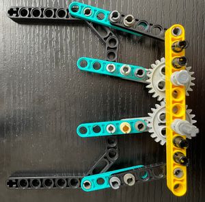
This highlighted that a parallelogram is what we needed so we could slightly decouple where the motor shaft is from where the gripper joints are, needed for this to be wide enough for the barrel and nicely place the servo motor and gears.
Danny sketched more, seeing this concept, considering what parts may be needed along with measurements.
At this point, it became very clear that this was going to be too complex for the time we had remaining. We needed to simplify this a long way.
Simplifying
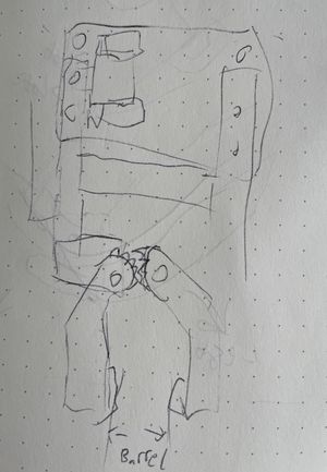
The next stage was to simplify the design. Danny had the benefit of seeing some other Pi Wars designs from their blogs, and that some had a simple set of forks that went under the ridges in the barrel. This would be a lot simpler to make. Once again, some more concept sketches, this time using calipers to measure the barrel.
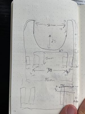
The forks now have some dimensions and measurements, so Danny could start sketching it FreeCAD.
FreeCAD building the grabber
The grabber forks could now be built in FreeCAD. Danny made them as an assembled part to go on the end of the lift arms. This was a simple design, but needed to be strong enough to lift the barrel.
This was made to assemble around the captive nuts above, along with clearing the camera and Pi Noon assembly. The height was set to fit under the barrels top ridge a little way, and the width was set to fit to the main diameter of the barrel below the ridges. Some fillets were added to make it look a bit more finished.
This made for a complete FreeCAD assembly of the attachment (using the draft workbench move feature):
We were ready to make and print the real one:
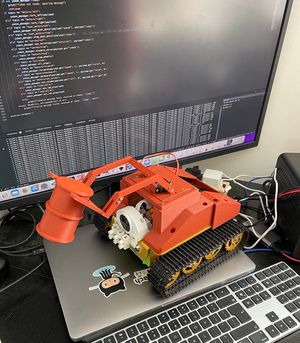
This looked really rather good.
Servo positioning
Initially, we set the servo position using the MQTT service on the Yukon, which let us find a neutral position, and then make sure that 90 degrees from it would lower the mechanism.
However, we’d later need to tweak that. We then started on the code.
The Code
The code for the servo motors was already in the Yukon service. Since there were 4 motor slots, instead of a fancy design to switch attachment types, we used the 4th slot, assuming the other 3 are the reserved for the nerf turret attachment instead.
This meant the main part of the code needed was the PS4 control extension for this. The PS4 service is another MQTT service, based on the approxeng.input library. It handles keypresses and analog movements, and then signals other services.
We chose L1 and R1 to raise and lower the grabber:
    if "r1" in joystick.presses:
        self.publish_json("servos/set", {"index": 3, "position": GRABBER_UP_POSITION})
    if "l1" in joystick.presses:
        self.publish_json("servos/stop", {"index": 3})
Grabber up was tweaked to be a value between 0 and 90, that would not fling the barrel off behind the robot. Although it was all a bit jerky, it was working.
Notice we had it set to off to put the barrel down. Initially, the down position put the barrel down with such vigour that it flung the barrel forwards. So using stop allowed it to slowly descend under gravity. Not ideal.
At this point, we needed tweening code, which we were able to adapt a little from code we’d written for the MeArm, and put this into the Yukon service. This would make a servo movement:
    async def move_servo(self, index :int, position: float, seconds :float =1, steps: int=100):
        time_per_step = seconds / steps
        servo = self.servo_module.servos[index]
        servo.enable()
        initial_value = servo.value()
        step_size = (position - initial_value) / steps
        for step in range(steps):
            servo.value(initial_value + step_size * step)
            await asyncio.sleep(time_per_step)
        servo.value(position)
This is an asynchronous routine, which will loop moving the servo in small steps until done. And in the mqtt handlers section:
if topic == "servos/move":
    asyncio.create_task(
        yukon_manager.move_servo(
            payload["index"],
            payload["position"],
            payload.get("seconds", 1),
            payload.get("steps", 100))
        )
The handler creates an async task from the above routine every time a servos/move message is sent (instead of the servos/set). It has sensible defaults, but we left it overrideable so we could tweak responses in the ps4 service or other behaviours.
Now we needed to modify the PS4 service to use this instead:
    if "r1" in joystick.presses:
        self.publish_json("servos/move", {"index": 3, "position": GRABBER_UP_POSITION})
    if "l1" in joystick.presses:
        self.publish_json("servos/move", {"index": 3, "position": GRABBER_DOWN_POSITION})
Using move instead of set gave us smooth movements, only now there was a new problem, the servo was sitting above the barrel. Grabber down was set to the full 90 degrees, but this was short of where it ended up. We needed to tweak the lift arm attachment to the servo spline, to get it to settle a little below, and the down position to put it above.
Servo positioning can be tricky, going past a limit and having the servo at stress will make it hot, jitter and may also mess with the power system. So Danny has an idea.
The Servo tweaker
Danny decided to make a “Servo tweaker”. After inspiration, Danny built a simple circuit using an Arduino, a 3 position male pin header, a potentiometer and a proto-board to build it. He’ll write more on that another time, but it was useful here to set the position of the servo to a safe position, and then tweak it to be just right, bolting the arm in there.
Conclusion
We now have an attachment that works, with the tuned code to control it, and cna lift and grab a barrel. See it in action in the video below: