A problem with Skid Steering is that that two motors of the same model, from the same company, and even in the same batch, may still not be identical. This makes robots veer off course.
This can be compensated for with sensors and code (like a PID algorithm) to keep the robot on track. This can be inefficient as the robot is constantly having to correct itself. You can also use mechanical methods to solve the problem.
What does it do?
The Adder Subtractor system uses sets of two differential gears to input power. There are input gears A and B, and output shafts L and R. The behaviour of the drive is such that:
$$L=A+B$$
$$R=A-B$$
Usage in a vehicle
Input A controls/powers the forward/backward motion of a vehicle, and is usually a more powerful motor.
Input B sets the difference so the robot can turn. When A=1 and B=1, R will be 0 and L will be 2, so the robot will turn with the right wheel as the turn center.
When A=0 and B=1, output L=1 and R=-1, the robot will turn on the spot, around the middle of the wheels.
The code to drive this is different from skid steer, and in some ways simpler. The code to drive this is:
def drive(speed, turn):
    left_motor.run(speed + turn)
    right_motor.run(speed - turn)
That turn value can be a direct output from a joystick, PID algorithm, or a simple proportional algorithm.
How Can You Build this?
This colourised picture shows the gear chain.
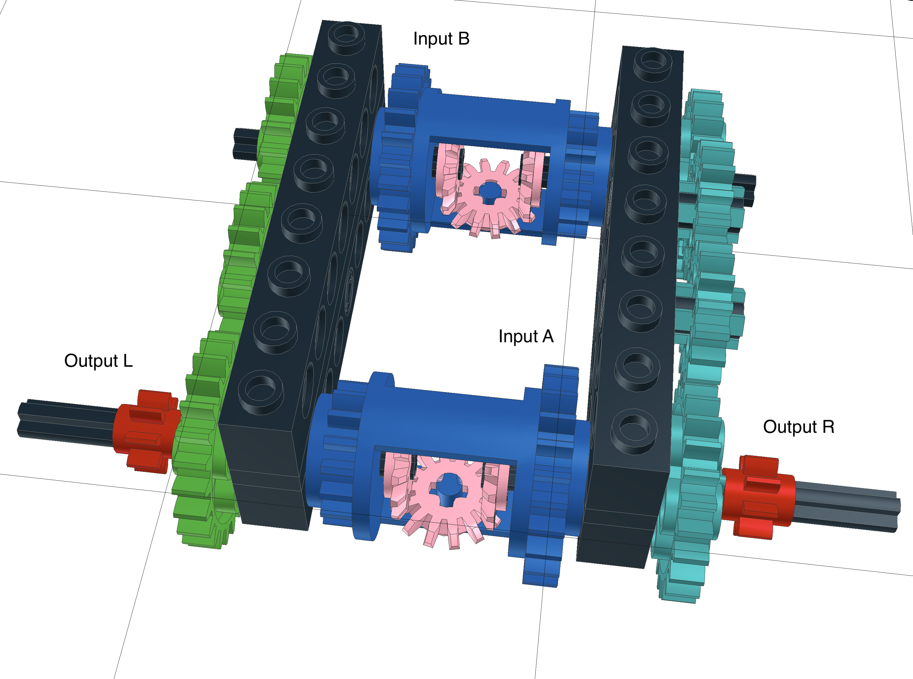
The differential gears are shown in blue, these act as the inputs A and B. The output axles have red gears on them, and are the outputs L and R.
There are two differentials, which are connected via the green and teal gears.
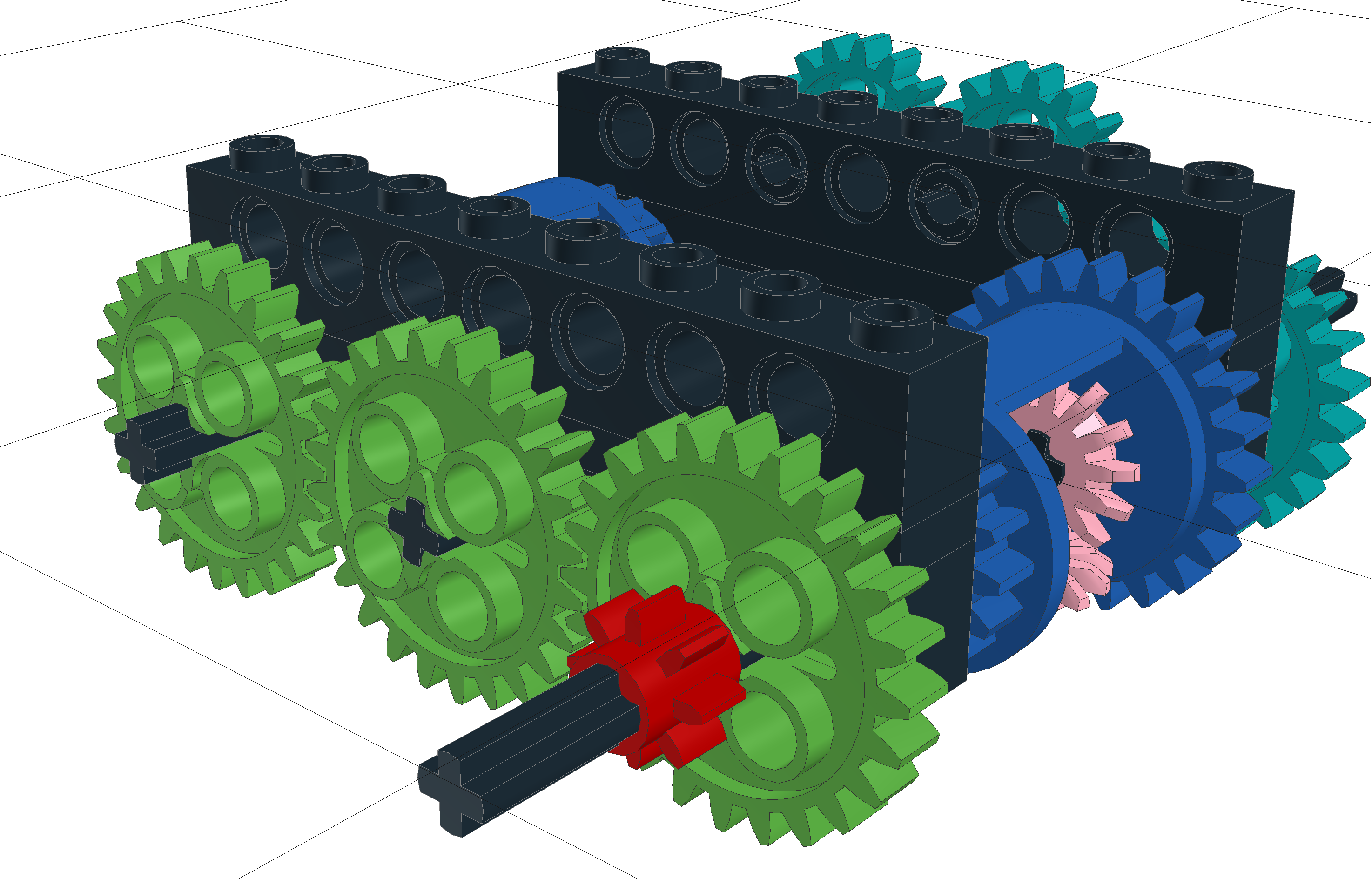
The left hand side with green gears:
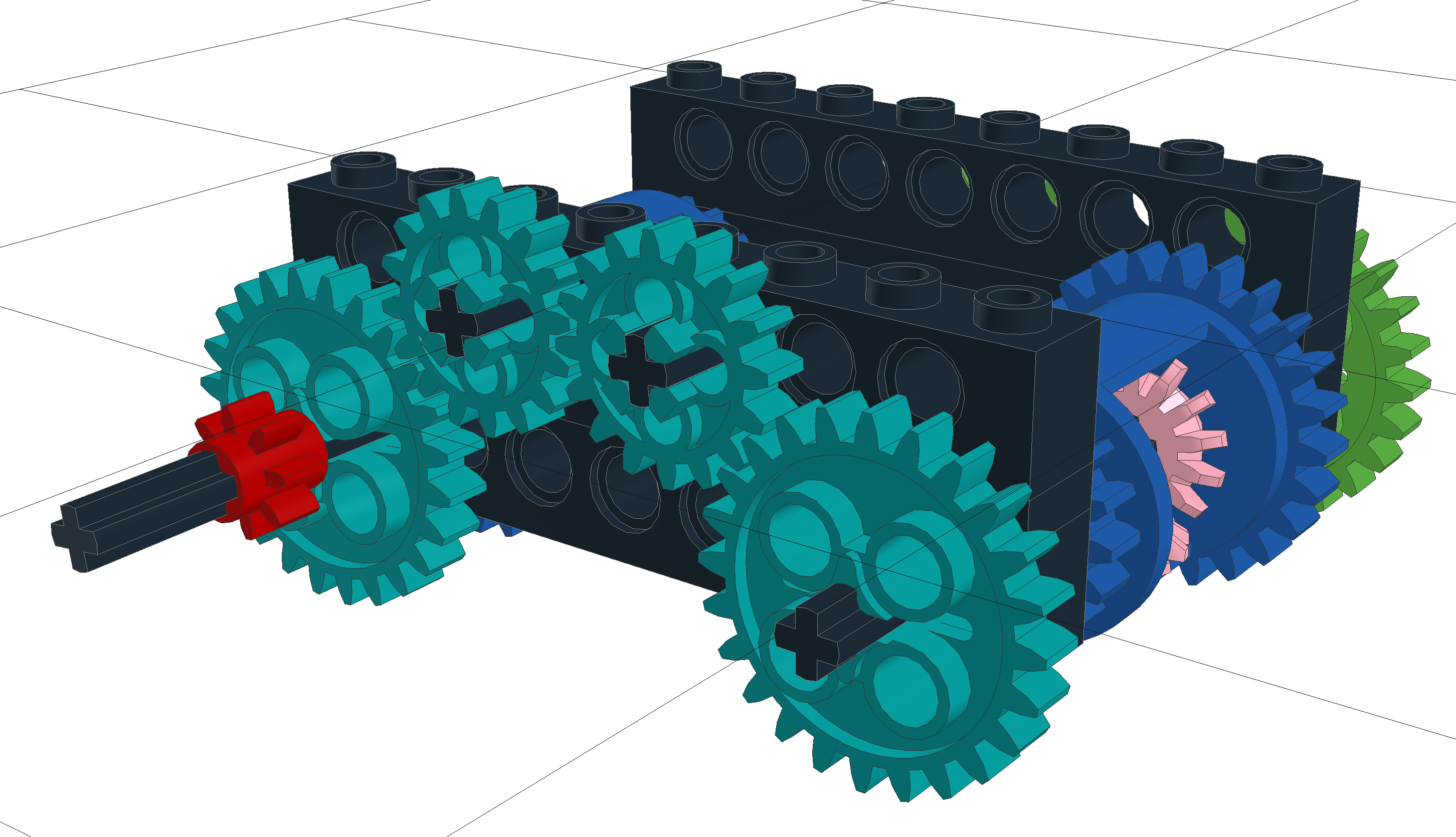
The right hand side with teal gears:
If we hold Input B still, and rotate Input A, the robot will drive forward:
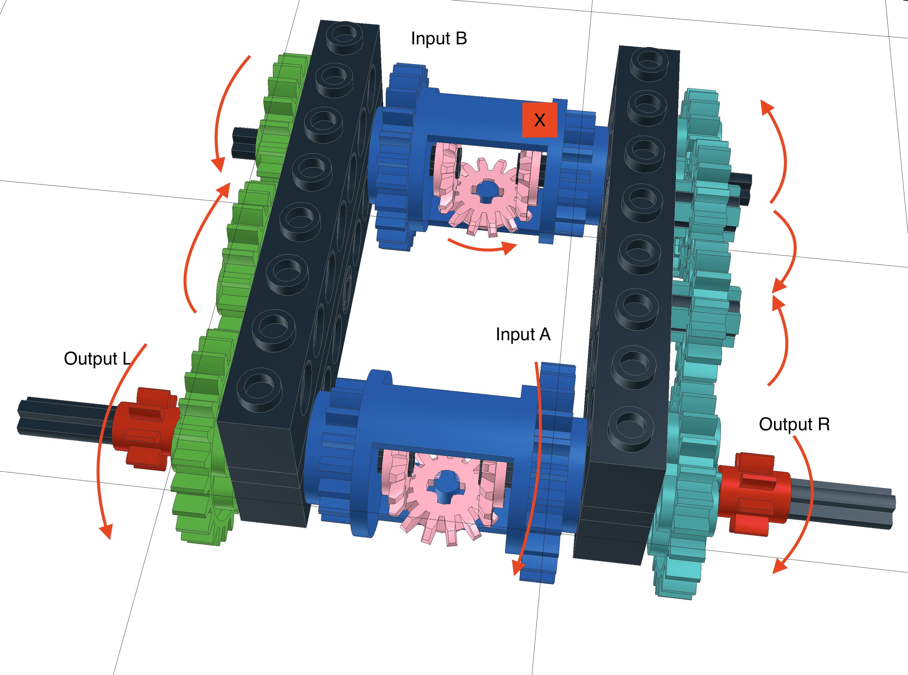
As input A turns, the left and right outputs will turn with it. This will be transmitted up to input B via the green and teal gears, the differential at B will handle them turning in opposite directions.
If we hold Input A still, and rotate Input B, the robot will turn:
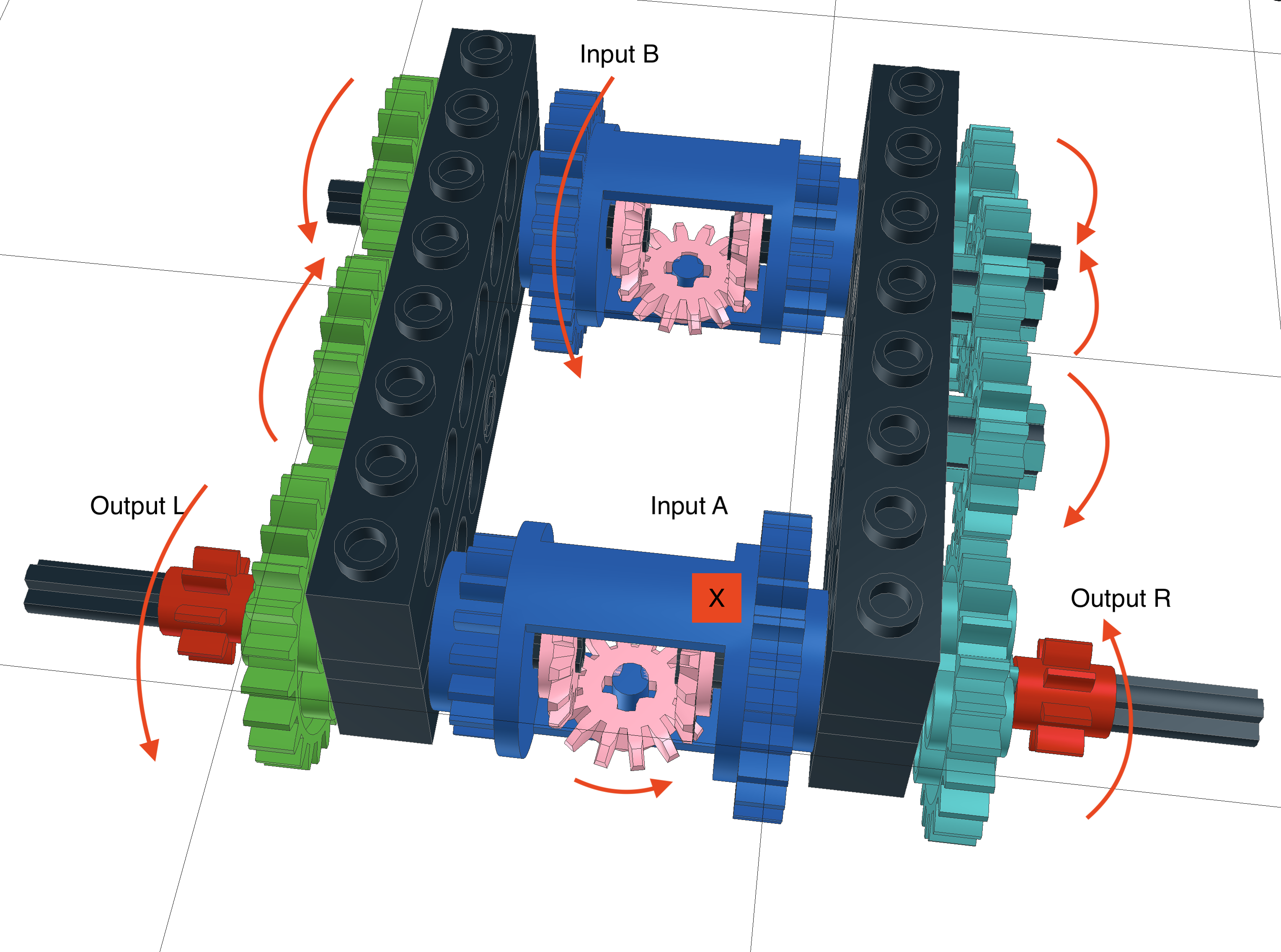
The left side has 3 gears in its chain, so the output will be in the same direction as the input. The right side has 4 gears in its chain, so the output will be in the opposite direction to the input.
The differential at A will handle the left and right sides turning in opposite directions.
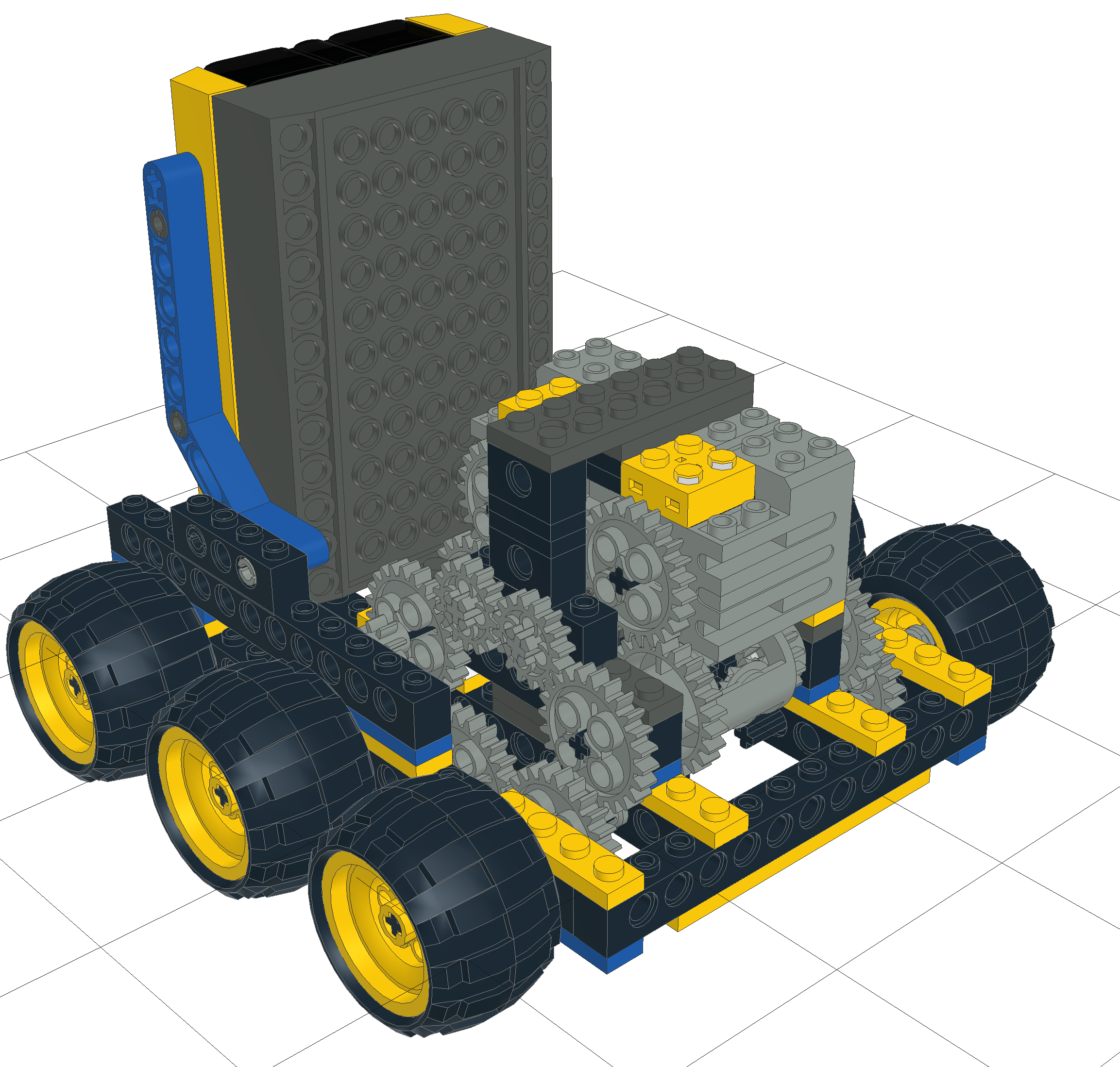
Lego Demonstration
An issue is housing this drive in a robot.
If you have an LDraw reader, please take a look at this file AdderSubtractorBuggy.dat.
Links for further reading
- http://www.mapageweb.umontreal.ca/cousined/lego/1-Varia/Adder/adder.html - Adder Subtractor Drives in Lego - Has a small design for this in Lego.
- For more on motor differences read The Brick Bakery: Analysis of Motor Speeds for Geared Motors..