Overview
The diode bridge is a common and useful circuit. You will see it regularly, and it is a construct worth being aware of.
How it works
Take a look at this circuit:
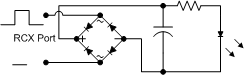
Examining this, you could substitute the RCX input for any AC input that has been stepped down to around 6-9v. The diodes form a small diamond shape -though not always in this clear form, it is better if you try to use it in diagrams as its purpose is then clear. There are two diodes facing cathode towards (arrow in) the positive DC line, and two facing away from the negative line. These are then connected to the AC inputs.
This means that when an AC input is positive, the diode connecting it to the positive line allows it through and you get a positive signal there, but when it is negative - then it is only allowed down through the diode connecting the input to the negative line. Having both lines connected like this means that as they reverse polarity, they conduct on opposite outputs - so the outputs are always at the same polarity.
Uses
It used for one of two main functions:
- Used with a capacitor to convert AC supplies to a DC one
- Allow a circuit to be used at any orientation (uncommon)
The first of these is found in just about every power adaptor (wall wart) you will come across. It is a very, very common circuit.
Orientations
Briefly examining the latter, you must be aware that there is a small voltage drop across each diode of around 0.6v giving a net result of a 1.2v drop. In a 9v application, that may bring the voltage below an acceptable level. The one place it is recommended is if you are building custom Lego RCX devices, which may need to be connected at multiple orientations.
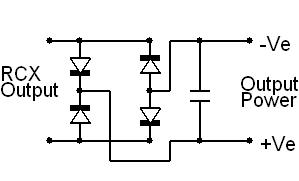
RCX output power circuit - click to Enlarge
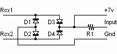
RCX Sensor power circuit - click to Enlarge
Planning one for your needs
If you are building a circuit with a bridge, you need to be aware of a few things. First, as mentioned above, the voltage drop. You will want to make sure that the input AC voltage is at least 1.2v above the amount you want. If this is a little over, you can always use a Voltage Regulator in the DC circuit to bring it down a little (say from 10.8 to 9v having used a 12v AC input).
Every diode has a reverse bias breakdown voltage. What this means, is that a certain voltage with the wrong polarity, a diode can break down and conduct anyway. You probably want to make sure your diodes breakdown voltage is a fair amount more than the required input voltage.
Also, you need to be sure that the diode you are using can handle the power requirements. You can work this out by estimating the current and voltage, then multiplying them. Again - to be safe, make sure its a fair amount above this - running it with a very close call is just asking for a damaged diode.
Take into account that at higher power levels, diodes may need heatsinks as like any high voltage circuit, they can get pretty hot.