A stepper motor is designed to move in defined repeatable steps, useful in situations where accurate positioning is needed.
They often have 4 sets of coils, and therefore 4 signal lines, and one common connector as shown in the diagram.
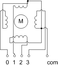
The diagram shows four coils, but in a real motor design there may be many coiled sections powered by each signal input. As you pulse the coils in order, the motor will rotate a small fixed distance. Motors can have around 120 increments per rotation.
The common connection may be positive or negative, and sometimes they have built in diodes to enforce this. To reverse the direction of the motor, you reverse the sequence of powering the coils, you do not reverse the voltage.
Remember that a stepper is an inductive load, and draws a fairly large current. They should not be used directly with a microcontroller, and should have some sort of power transistor circuit, flyback diodes and capacitors - a motor driver/controller board typically has all of this.
Uses
Industrial robot arms mostly use stepper motors, although in smaller ones and hobbyist devices, servo motors can be simpler.
They are often used in spinning disk drives, printers and scanners for moving print heads.
Having odometry systems with geared DC motors, is an alternative found in many robots.