If you are working with small devices, you will need power supplies for them. 5v is generally easily supplied by a USB port (be careful here - get it wrong, and you may damage your laptop). 3.3v needs a few tweaks.
I wanted to power the esp8266, and it took a few attempts to get it right. I’ve got footage, circuit diagrams and datasheets for each attempt, the limitations of it, and details of what worked brilliantly.
Attempt 1 - Using the TS2950CT
First up - the TS2950CT - capable of 150mA max (this was the flaw). This is an easy to use regulator in a small TO92 package - which has 3 pins, is easy to breadboard, and was available in a local Maplin.
It is “Ultra Low Dropout”, so 5v+ is ample. Only a single 3.3uF cap was needed to get stable output from it.
However, after having this work, I had to order a new serial cable to talk with the 8266. When that arrived, I attempted to use it with the 8266.
It didn’t quite go right, I found it not particularly responsive - garbage characters and then a reboot loop - I diagnosed the power supply as being the problem.
After some research, and checking current with a multimeter, and the datasheets for the chip along with information on the 8266, it became clear that this supply is underpowered for the esp8266.
Datasheet for TS2950CT: http://www.farnell.com/datasheets/50395.pdf The 8266 can need 240/300mA when wifi is enabled.
Attempt 2 Powering it with An Arduino Uno R3
As a short term hack to get something, anything other than the reboot loop, I used an Arduino Uno rev 3 board to power it - this worked ok, but is a bit of an abuse of an Arduino, and according to it’s datasheet, it was barely better than the original, but at least just enough not to be in the reboot loop.
Specifying the actual power converter to use
I spent a bit of time choosing and checking the specification for a power regulator - inspecting the datasheets for it.
The part I chose: http://www.farnell.com/datasheets/1776449.pdf
Getting it to work
Finally, I received this part, built a circuit board with it and got the 8266 running, without tracebacks on it. This was the part used in all my further esp experiments.
The part I chose, the LD1117 worked brilliantly and has power to spare for other sensors or devices on a gadget.
Here is the circuit in fritzing:
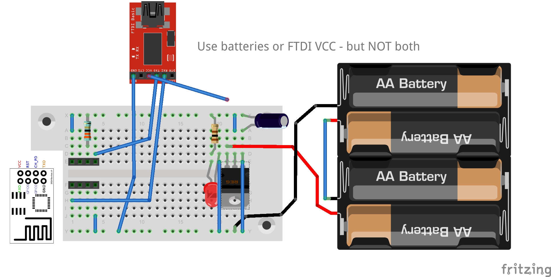
BOM:
- ESP-01 Module
- Serial/USB cable - the FTDI brand was popular for this, although they may have recently fallen out of favour due to loosing control of their supply chain and bricking people’s stuff.
- Red LED + 100 Ohm resistor (optional for power indicator)
- Breadboard
- 330 Ohm resistor for CHPD Pull Up (on ESP)
- 10uF Capacitor
- LD1117 3.3v voltage regulator
- Bunch of jumper wires - breadboard type, and male-female type.