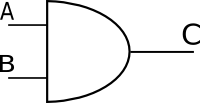
AND Gate
This is a Boolean operation, which gives a result of true only when its first input “AND” second input are true (in the case of a two input AND). It is used both as an electronic element and in programming.
A Truth Table for this operation:
| Inputs | Output | |
|---|---|---|
| A | B | C |
| 0 | 0 | 0 |
| 0 | 1 | 0 |
| 1 | 0 | 0 |
| 1 | 1 | 1 |
Note that AND gates with more than two inputs exist. The rule for them is that the output is only true when all the inputs are true. These are very useful for simple pattern matching - Ie a logic element only active with a certain input.
When would I use this?
Like all boolean operations, it is useful for evaluating certain conditions are true. Say you want a robot to only move forward if there is sufficient battery power, and there are no obstructions.
It also used for clocking. if you have a circuit which may at any time generate a true condition, but you only want the next circuit to act on it when there is a clock pulse, then you use an AND gate to combine the clock signal with the other signal. This is regularly used to synchronise the operation of digital circuits.
Combined with NOT and OR you can build extremely complex logic. It is this logic, in fact, which drives your home computer, your mobile phone and most other digital apparatus.
Building a simple AND gate demonstration
This concept can be easily demonstrated with a circuit, with a prop that takes minutes to build. This is a great small project for children, suitable for parents and educators.
Required Materials
- 2 Electrical Switches/buttons - push to make
- Some jump leads with clips or a breadboard.
- A power supply (approx 5/6v) - A bench supply or fresh batteries will do
- An LED
- A Resistor (around 470)
Optional Materials
- Mounting cardboard
Required Tools
- Soldering Iron + Stand and Solder
- Clamp/Helping Hands
- Safety Goggles
Optional Tools
- Cardboard cutting scissors
- Pens
- Multimeter
Building it
There is only a little soldering here, and if you have built the Simple Parallel Port LED Board, you may not need to do any soldering at all. Note though, because of how little there is, the soldering will be Freeform.
You need to take the LED and identify the Anode - this is the cable on the opposite side to the flat edge. Using the clamp to hold the cables in place, solder the resistor to this lead.
Now clip the jump leads to the switches - wiring them in series. This means the positive rail from the power supply must be wired to the contact on one switch, the next contact wired to a contact on the next switch, and the following contact wired to the resistor (on the LED), and the Cathode of the LED wired to the negative rail on the power supply.
I then suggest you mount the demo on a piece of card - labeling one of the switches/buttons A, one of them B, and then labelling the LED C. If you are feeling fancy, you could then draw the Logic Symbol for the and (As shown above) between them.
Testing it
Apply power to the circuit. The LED should be turned off - if it is already on, check that you have not used push to break switches.
Now try the combinations. Turn A) on, the LED should remain unlit, turn A) off and B) on, the LED should still remain until.
Finally turn on A) and B), and the LED should light. If the LED still does not light, I suggest you first check the power supply, then check the switches, and your connections to the switches using a multimeter. Check that you have not used to high a resistance, and check your power alone lights the LED.
Demonstrating with it
You can then use this prop to show that the LED only lights when both A and B are on - providing a test of two separate conditions. If you use a simple situation role play, you can quite easily convey the principle.
Example Situation:
You are in the canteen, and you are deciding if you should buy food there or somewhere else. A basic condition to meet is that A) The canteen is currently serving a dish you like, and B) You have enough money in your wallet. You would only buy food if both of the conditions were met.