Introduction
When you are experimenting and attaching to the Parallel Port, you probably do not want to buy many DB25s, but rather connect to them easily and effectively.

Soldering directly to the DB-25 pins on a Male connector is a bad idea, they are not too cheap, and there is no point throwing one away after making one test circuit. This would also mean that you need to reach behind your PC every time you want to experiment.
Our solution is to build a small cable between a 26 pin ribbon connector (aka IDC Socket) and the DB-25. I recommend using the push down types which bite into the cable - soldering this all would be far too fiddly (fancy making 50 connections?), and crimping can be a pain too.
This cable was used for the Simple Parallel Port LED Board and can be used for and further projects.
Please read the Robot Building Safety guide, and then the Tools guide before continuing.
Required Tools
- A Soldering Iron
- Solder
- Small Clamp or Helping Hands
- Safety Goggles
- Clothes you don’t mind getting solder on
- A good workspace with good lighting.
- A Multimeter
Required Parts
- One DB25 Male socket - preferably the push down type for ribbon cables. They normally give an easier, and neater result than soldering.
- One 26 or more pin IDC socket - again - get the push down solder free type.
- One 26 core ribbon cable - preferably in single colour with one Red Line for pin1.
Building the hardware
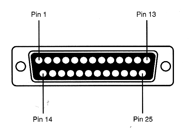
Take the ribbon cable, and line up the Red Wire with pin 1 on the DB25. Then push down the DB25 making the connection. You then line up the IDC socket on the other end, and push down too. Try to make sure the ribbon strands are lined up well with the teeth of the push down connectors.
Testing it
Using the multimeter, systematically test the pins on the DB25 making sure that none of them are shorting with any neighbours. Then testing that each pin on the DB25 links to a corresponding pin on the IDC.