The resulting waveform:
The diode bridge is an essential part for making active sensors for the Lego Mindstorms RCX. It is also known as a full-wave rectifier as it will rectify AC current into DC, or (as in the case of the Lego connector), allow something to be connected at either polarity, even with fairly complicated circuitry. It does come with a minor disadvantage in that the voltage is dropped a little across each diode, and where possible, a mechanical means to guarantee polarity may be better.
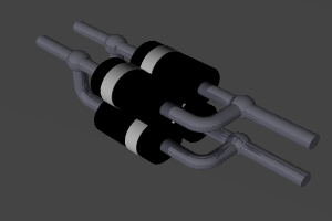
A rectifier bridge can take up some space, and so freeforming it is an interesting way to save some. The intention was to make a diode bridge small enough to fit in a Lego brick, so it can be used for active RCX sensors.
Building this is a simple introduction to the concept of freeforming circuit blocks and can be used for other circuits with some imagination and thought. It requires no PCB, or veroboard, mostly just the components and a good iron. The full tool list is below and minimal.
Before connecting anything to an RCX, or any other system, be sure to test it. I’ll discuss a few different methods of testing the module below.
What is the diode bridge?
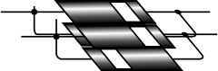
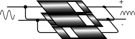
This circuit rectifies a waveform oscillating around 0 such that it is now oscillating only above zero. It does so by using diodes - which allow current to flow in only one direction. These are set up in a group such that in the output from this one pin is always negative, and another is positive.
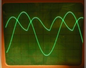
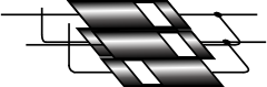
The two wave forms superimposed:
I do not have a dual trace oscilloscope, so this was the only way to do it.
I note that the calibration of the scope has changed between the two measurements - but lets examine the results ignoring that.
There also appears to be a DC offset on the diode outputs - not sure about that, given that I took it off the sine wave, however I can reason that it is shorter due to the 1.2 volts or so used by the bridge itself. The fact that the peaks are symmetrical shows that it is balanced and stable.
In fact - if there was a DC offset on the input waveform, there would be two different sets of peaks - so it may merely be down to the dial on the oscilloscope. Any other explanations you could offer?
If you look at the scope output - with the input wave and the converted wave superimposed (done later with a graphics program, and try to ignore the phase here), you will see that peaks and troughs both become peaks on the output waveform. It is worth noting that the diodes do also have a voltage drop across them, so the peaks of the output are less than the peaks of the input.
This circuit is most commonly used when converting an AC source to a DC source, and then with a smoothing cap to change that sawtooth like waveform into a smoother line waveform.
In the context of the RCX, where the pads for connecting sensors and outputs are not polarised, the output may be connected in any orientation, so this also safely ensures that the voltage ends up at the right polarity in your circuit. It is your decision in deciding if the space consumption and voltage drop are worth making for the ability to be able to plug in at any orientation.
By freeforming it you can reduce how much space it takes up. As an alternative, modern electronics stockists now carry a single rectifier bridge component.
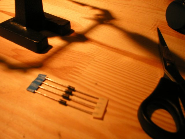
Tools You Will Need
When you build anything, be sure to do it with the right tools and do it safely. I’ve tried to keep the tools to the minimum here, but make sure you do have the basics.
Tooling Up Safely - Goggles
Basic Safety
- A solid, well lit desk space, free from clutter and interruptions.
- A pair of safety goggles
Goggles - I know many people hate them, but trust me - after having ended up with dry paint flakes in my eye once, I seriously value these - I had to actually go to a specialist eye hospital to have that removed. that was paint. Hot solder would be considerably worse. So - look after your eyes - they are probably the most valuable thing you have after your brain. They are also quite a convenient entry point to your brain too - another good reason to keep them covered!
Tooling up - Stuff to do the job
- A soldering Iron - you will not get far without one of those.
- A sponge & Holder for the soldering Iron
- Long nose pliers - you’ll need these to make the bends in the wires.
- A positionable mini-clamp - aka Helping Hands. There is some pretty tricky soldering, so unless you have 3 heatproof hands - this is essential.
How to Freeform it
Choose your diodes. Read Diode Bridge to ensure that you understand how the circuit works, and that the power rating and electronic characteristics are suitable. All 4 should be identical, and have longish leads. A type suggested are 1 amp 1N4001. These are simple general purpose rectifiers - ideal for this.
If you can find diodes on bandolier tape, as those produced by Maplin and other electronic component retailers are sold, this will make your life easier later, but it is not essential though.
Method
Be sure you are wearing your safety goggles for this. I would strongly recommend reading this guide Robot Building Safety.
Step 1 First Bend
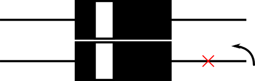
Use pliers to make a bend in one leg of a Diode at the red X.
Needle nose pliers should give a nice clean bend. Leave a little curvature in it - too sharp a bend may become weak and snap.
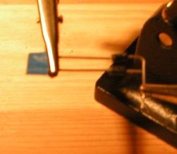
Step 2 Solder the legs
Solder where the legs cross. There should be some of the leg sticking out from then end, this will be one of the contacts for the module.
This is tricky - use the helping hands to hold it all together, and use one hand for the iron, and the other for the solder.
Step 3 Trim one leg
Cut off the excess going out to the side. Trim as close to the solder joint as you can, but don’t snip the joint.
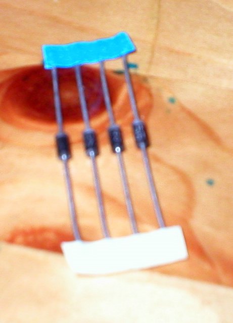
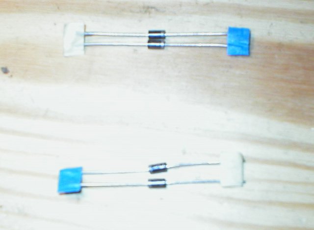
Step 4 - repeat for an opposite pair
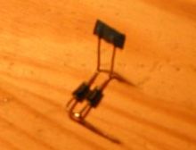
The pair should look like this.
Repeat this on the opposite end for two more diodes. You should now have 2 diodes joined at their cathodes, and 2 more joined at their anodes.
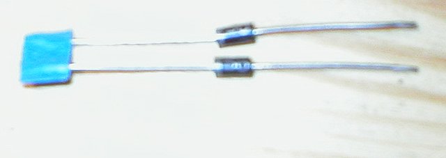
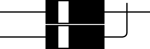
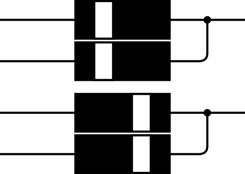
Step 5 - Bend one set of legs upwards
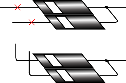
On only ONE set of diodes, bend the legs upward at the red crosses.
Note - Dont Trim yet!
At this point - I trimmed the legs on the other set. I don’t advise this, and suggest to actually wait until having soldered them to trim them.
Step 6- Bring the two pairs together
Now bring the two pairs together. A dab of glue between the layers, allowed to set will make the next step easier. Be sure that the legs from the lower set are touching the upper set.
Step 7 - Solder the lower legs to the upper ones
This is a very tricky step. Using the helping hand clamps to hold the diodes, solder the lower legs to the upper legs where they cross
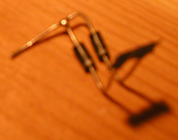
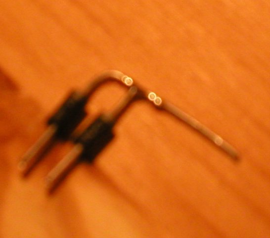
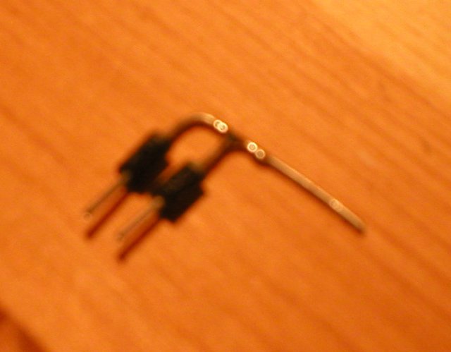
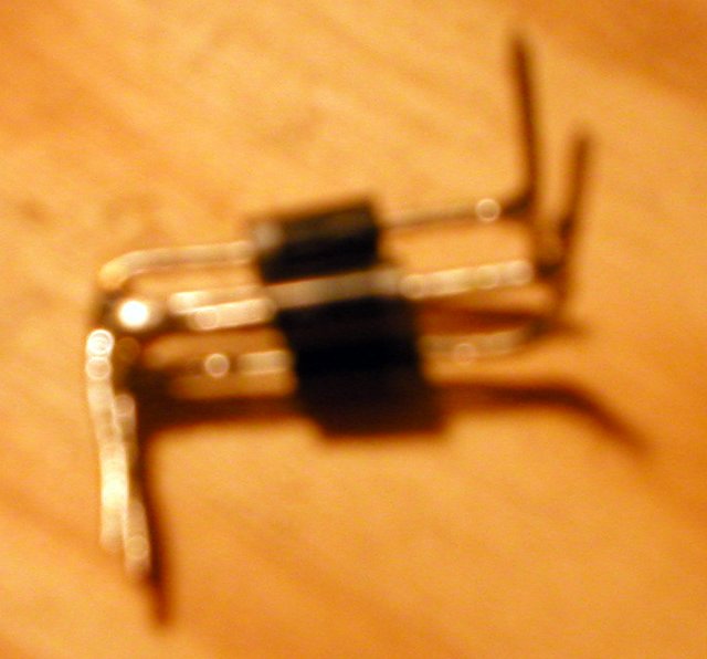
Step 8 and completion
To complete the module, trim the excess off the legs. The bridge is now ready to be used in a circuit.
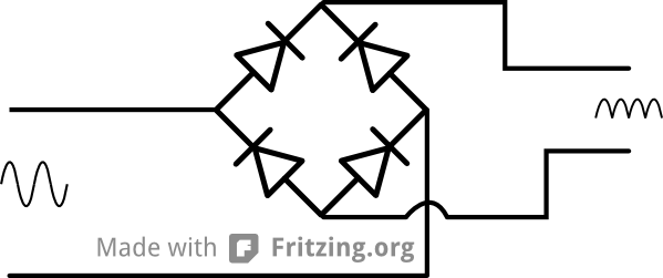
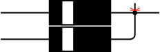
The diagram shows the connections - be sure to observe the polarity on the output.
Testing the diode bridge
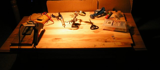
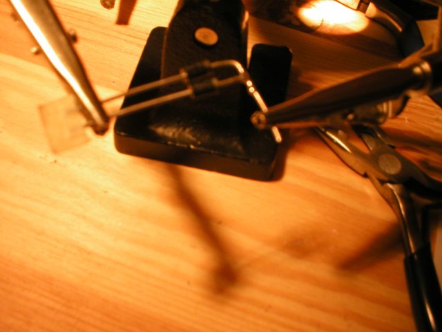
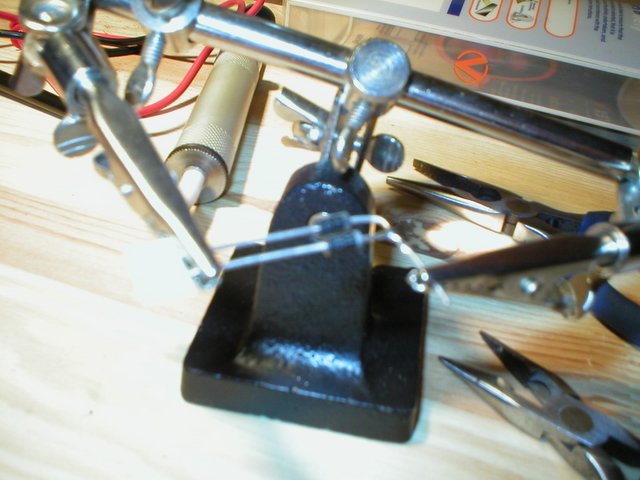
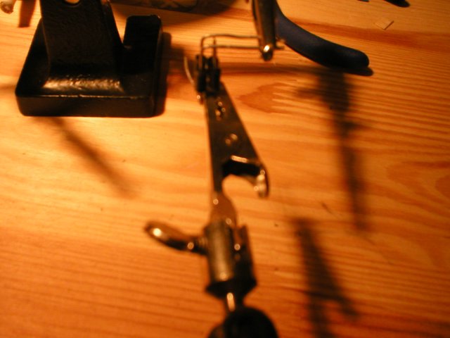
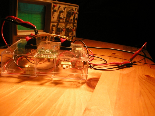 Here you get a good view of the full rig, including one of the better shots of the signal generator (in the transparent box).
The freeform bridge is tiny in the jump-leads, enough that I nearly dropped and lost it. That is a good sign though - it means it is likely to fit in a Lego brick.
I tested mine with an Oscilloscope and a sine wave from a signal generator.
First connect a power source to the signal generator, and the output of the signal generator to the input of the bridge. I then used croc-clip oscilloscope probes to connect the output of the bridge to the Oscilloscope.
It is worth having a dual trace oscilloscope, so you can see the difference in the signal from the generator, and after it has been filtered by the bridge.
In the picture - the large transparent box is my signal generator - a small Velleman kit one + an amplifier. The freeformed bridge is tiny and barely visible in the photo compared with the bench kit to test it.
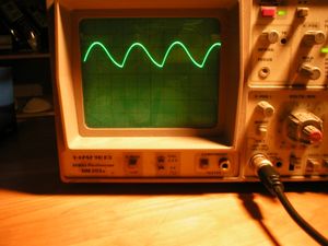
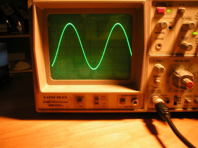 This is my oscilloscope showing the full wave generated by my signal generator - its quite clean.
![]()