In the last post, I looked at the Raspberry Pi Electronics in the robot. Today I’ll look at the Arduino side.
The motor control and IO board is a 4tronix 4duino Pro that was kindly donated to Orionrobots by 4tronix along with this amazing Devastator aluminium tank chassis used in Big Ole Yellow.
The 4duino pro roughly follows the outline of the Arduino Uno, so I’d built this back in 2019 using a protoshield variant from GikFun.
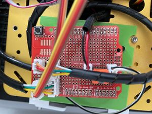
The is the board from GikFun Protoype Shield DIY kit with my customisation. The following image shows this board on the robot, it’s loose since I had to take it off to inspect below the board:
Unlike the Raspberry Pi board, I had not quite documented it as clearly. There isn’t a Fritzing part for this, so my original attempt in 2019 was to use another protoshield model in Adafruit plus a stripboard to represent this.
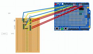
This is a pitiful representation, but was used for the soldering. Although I definitely changed it as I went. I’ll need to document this better. My plan is to document what is really there now in Inkscape, otherwise, the only source of the wiring is the board and problems are going to be very tricky to spot.
As mentioned above, I had to remove the board from the 4Duino to get a good look at the underside here.
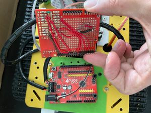
In the picture, first notice the 4duino pro, a good look at this makes me wonder if I could find a way to better utilise the nicely broken out pins there. None are quite set up for i2c though. You can then also see the horrid hacky wire soldered to the jack connector - this is the power for the Arduino. I’ve missed a trick in that this jack voltage in is connected through to the vIn pin. The schematic for the 4duino helped confirm that as a future improvement.
The wires on the underside are a bit of a point-to-point mess. They are not color coded.
I used Inkscape to create a fresh diagram of the board - which took a few hours. I used a photo of the Gikfun board as a background so I had an exact match of the layout.
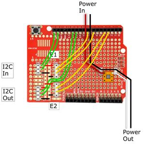
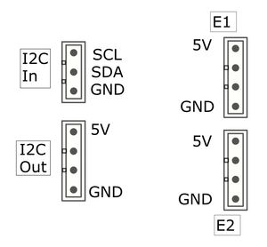
This is still a pictographic (not schematic) layout, but it matches roughly what is there, the switch part is not quite right. It shows the i2c input connections, E1 and E2 are the encoder inputs, and then there is a power switch intended to go from the motor battery power through to the Arduino. The Arduino is powered by the 5v regulator on the 4duino pro.
I found it helpful also to make tables for the connectors:
These are a start to understanding what I’d built. However, tomorrow I think I’ll build schematics in Kicad and block diagrams to make it easy to explain the blocks here - it’s not that complicated at that view.