Raspberry Pi Pico Session with Mini Orionrobots - LED flashing and speaker tones.
I’ve been playing with the Raspberry Pi Pico a lot lately, and Mini_orionrobots (aka Helena) joined me. In this article, I’ll examine what we got running with the Pico and how the session went.
The Raspberry Pi Pico
I’ve not written much on the Orionrobots channel about the Raspberry Pi Pico, but it is a really awesome device. It’s a microcontroller - capable of running code to control physical hardware. It’s also pretty small. With a breakout board not so different from an Arduino Nano in size.
The Raspberry Pi pico runs at 133Mhz, with dual cores. It is able to run MicroPython and Circuit Python, so it’s very suitable for teaching aspects of text coding with kids. It’s a great tool to learn electronics, robotics or microcontroller programming at home with.
It’s also only £3.60 - so I’m very happy to let my kids code and connect things to it.
Starting point
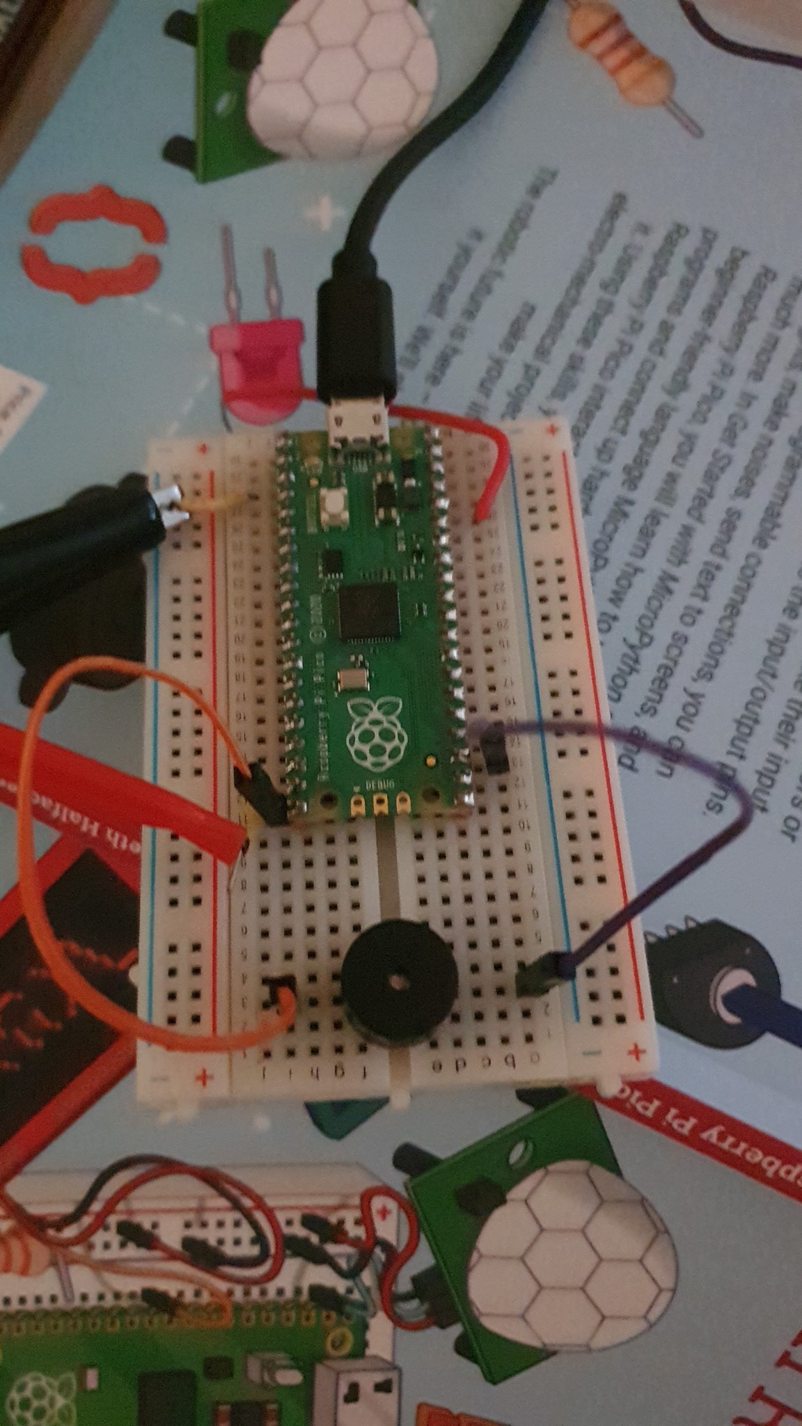
This Pico already had headers soldered on, and I had previously put MicroPython on it.
I gave Mini_orionrobots the Pico, some breadboard, and showed her a selection of sensors, LED displays and things she could connect it to. I asked her what she would like to do first. Her choice was that she wanted to see if she could make it make noise.
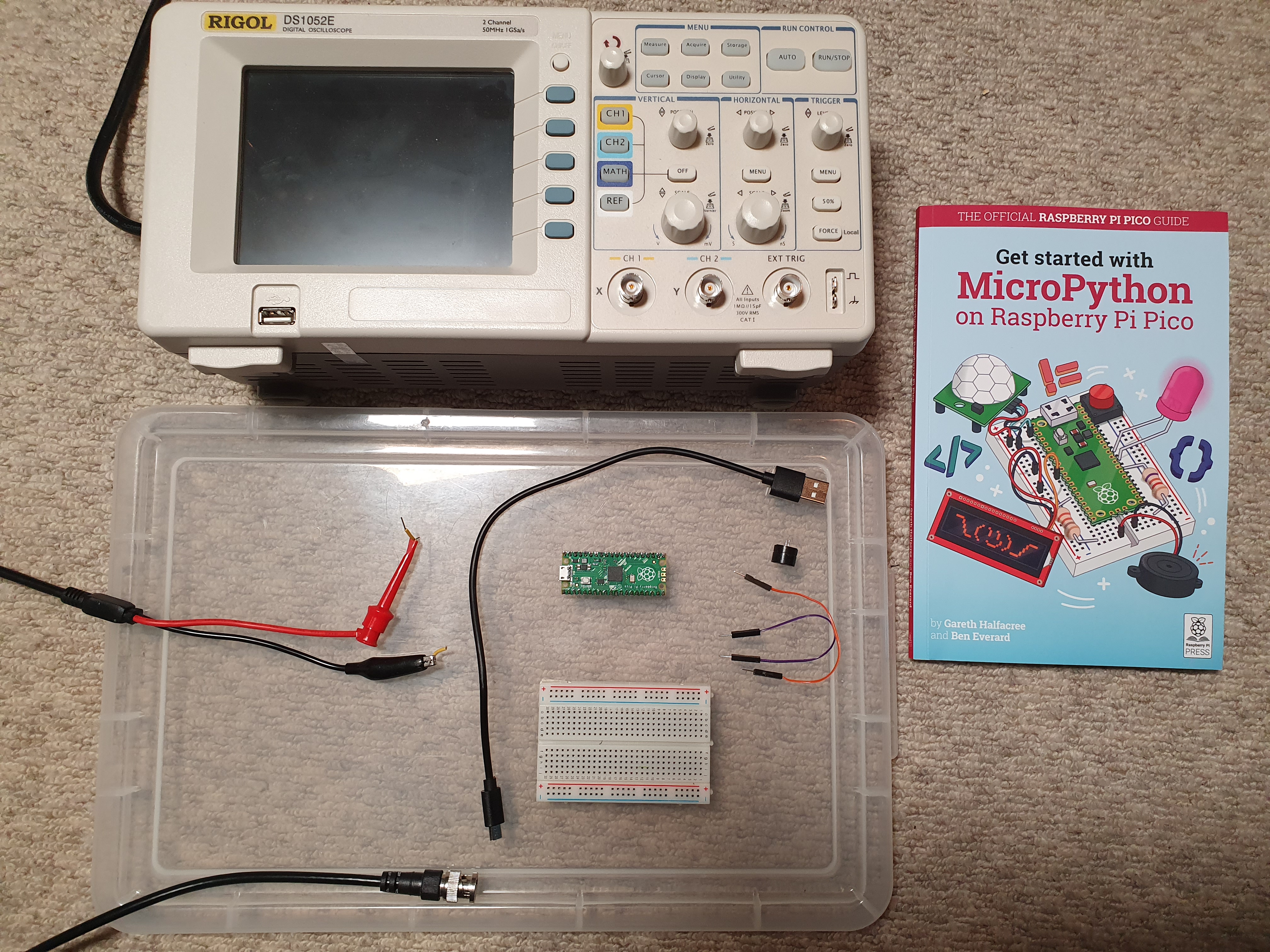
The materials we used today were:
- A Raspberry Pi Pico with headers soldered on, and MicroPython on board.
- USB micro cable
- A breadboard
- A tiny beeper/piezo speaker
- 4 male to male jump wires
- “Get Started with MicroPython with on Raspberry Pi Pico”
- A Digital Storage Oscilloscope - I used a Rigol DS1052E
- An oscilloscope probe with croc clip and spring clip
- A Laptop with Thonny installed
Awesome - lets do this!
So we talked about the first steps with a new controller, and I suggested making a blinky - that is a blinking LED. She was enthusiastic.
Making a blinky
We have a copy of the excellent book “Getting Started with MicroPython on Raspberry Pi Pico” from the Raspberry Pi Press. This was used a reference, with the diagram of the pins bookmarked for frequent use. I really should put one of those on the wall.
We worked through the “Hello, LED!” example in Chapter 4, getting the built in LED on GP25 to light. She played with turning it on and off. Mini_orionrobots is already familiar with variables. First she was manually flipping it on and of, then we carried on to the section importing utime, and created a while loop.
This got her a simple flashing LED. She was then playing with the light. It was from here that we started diverging from the book.
Talking Frequency
I left it with the value(1) and value(0) calls here, to lead us to later experiments. First I asked Mini_orionrobots what time she would need to put the LED on for and off for to blink 5 times a second.
Her first guess was to turn it on or 0.2 seconds, then off for 0.2 seconds. However, this means it is blinking a 2.5 times. I got her to think about it, and se that we need 10 LED changes a second to get 5 blinks per second. This means that it should be on for 0.1 seconds and off for 0.1 seconds. She got this working.
I now asked what she would do if she needed to change the rate? She first did the division by hand, but I reminded her that this is a computer, and that it could do theses calculations for her. She understood:
import machine
import utime

led_onboard = machine.Pin(25, machine.Pin.OUT)
frequency = 5
sleep_time = (1/frequency) / 2

while True:
    led_onboard.value(1)
    utime.sleep(sleep_time)
    led_onboard.value(0)
    utime.sleep(sleep_time)
She can now change frequency to get it to different speeds. She tried 1, 0.3, 30, and 100 - where she could no longer see the LED pulsing. She couldn’t see it changing now. So I suggested it was time to bring out a bigger tool… The oscilloscope.
Monitoring with the Oscilloscope
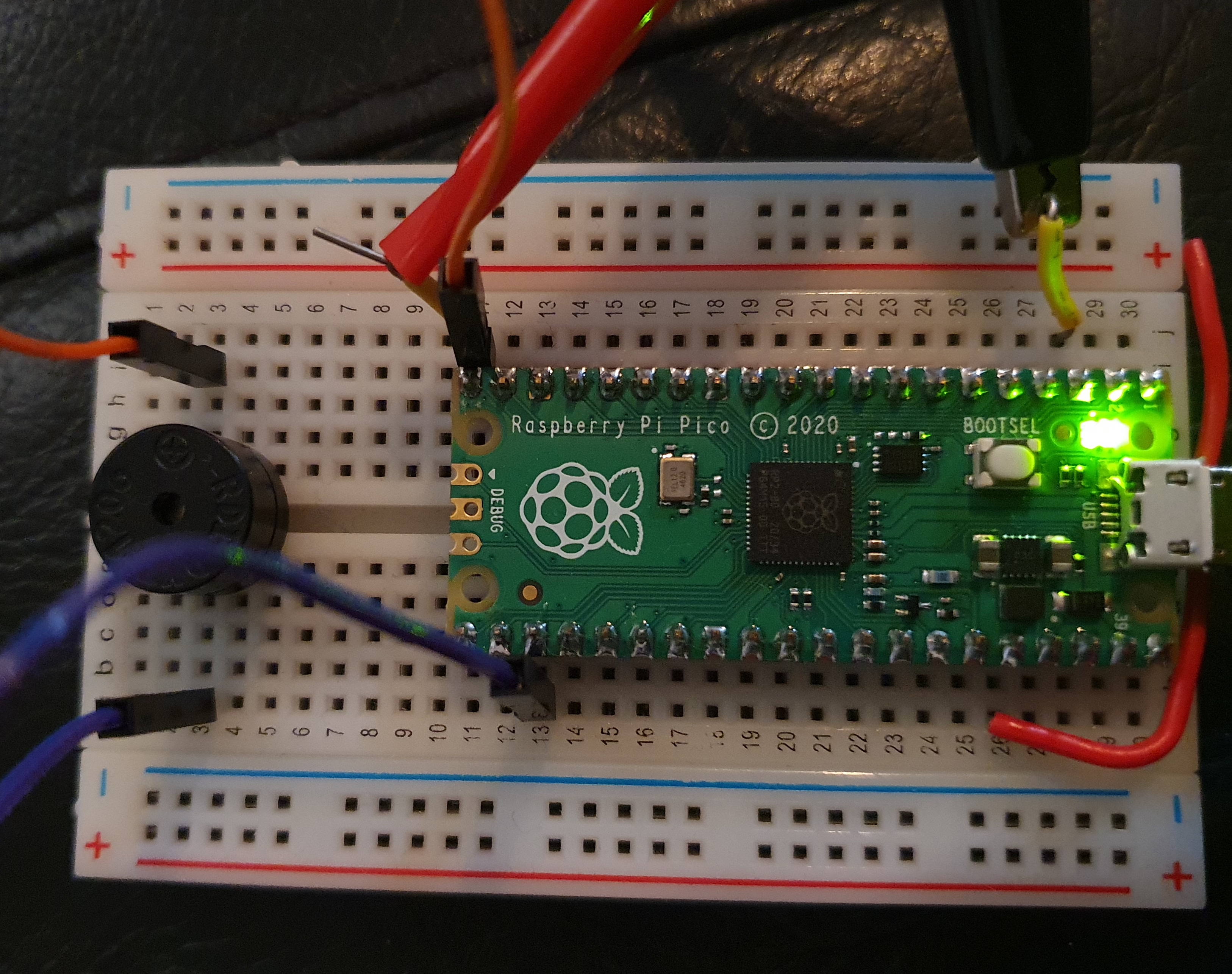
Mini_orionrobots is always excited when the Oscilloscope comes out - it has a colourful display and many buttons. It was at this point we plugged the Pico into a breadboard.
We set up a connection to ground, and then used GP15 as a monitor pin to connect our probes to. The idea being to make the same change to the monitor pin as GP25. This way we can see what signal is being sent to the LED.
import machine
import utime

led_onboard = machine.Pin(25, machine.Pin.OUT)
monitor = machine.Pin(15, machine.Pin.OUT)
frequency = 5
sleep_time = (1/frequency) / 2

while True:
    led_onboard.value(1)
    monitor.value(1)
    utime.sleep(sleep_time)
    led_onboard.value(0)
    monitor.value(0)
    utime.sleep(sleep_time)
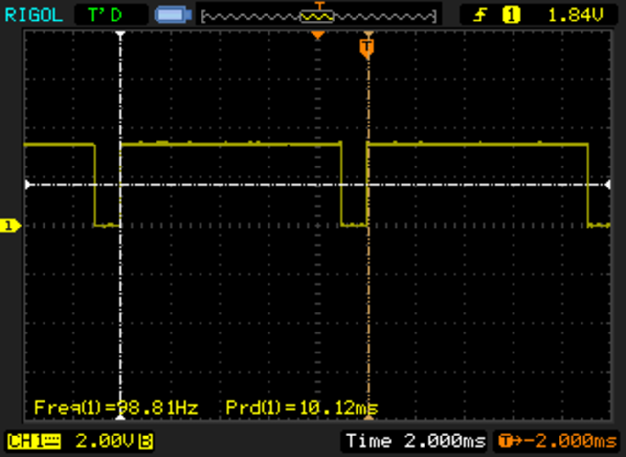
We turned on the oscilloscope, powered on the scope and then the Pico. We then started the code. What we first saw:
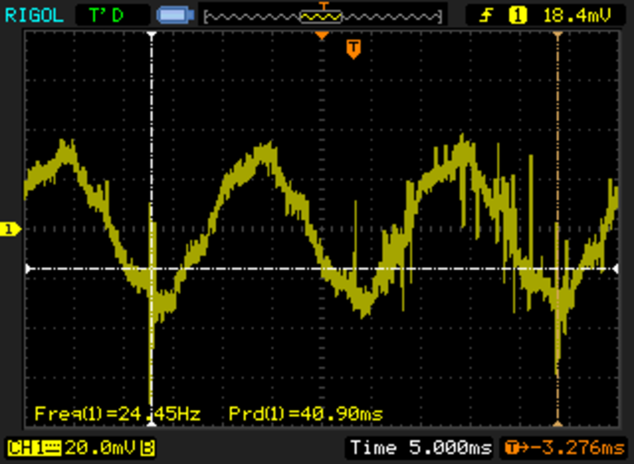
This was a curvy sine wave, at the wrong speed (50Hz), and the wrong voltage size. Not what we were looking for. I then checked all the connections again - and found that the ground pin was not properly connected. Whew. We then got a square wave - at this point at the frequency of 100 hz. Yes - I explained that term - cycles per second.
Looking at the captures, we can see a few things - first we have a couple of complete waves on the screen. The rate below shows the frequency at close enough to 100hz. The vertical axis is the voltage. From bottom to top we can see it is 3 and bit squares tall. This is the expected 3.3v from the Pico’s output pin.
Mini_orionrobots found this exciting. I then asked if she could make the LED brighter. She wasn’t sure how - maybe bring the frequency up. This didn’t really help - but we could see it on the scope.
Introducing a duty cycle
I suggested that she could change how much time the LED was on in relation to how much time it was off. They didn’t have to be equal. She got this. I spoke about hwo being on for longer would effectively mean there was more power going to the LED, so it would be brighter. I know this was a tangent to sounds, but since we had the scope, it seemed like a fun direction to go in.
I suggested she add an on time, and off time variable:
import machine
import utime

led_onboard = machine.Pin(25, machine.Pin.OUT)
monitor = machine.Pin(15, machine.Pin.OUT)
frequency = 100
on_time = 0.5/frequency
off_time = 0.5/frequency

while True:
    led_onboard.value(1)
    monitor.value(1)
    utime.sleep(on_time)
    led_onboard.value(0)
    monitor.value(0)
    utime.sleep(off_time)
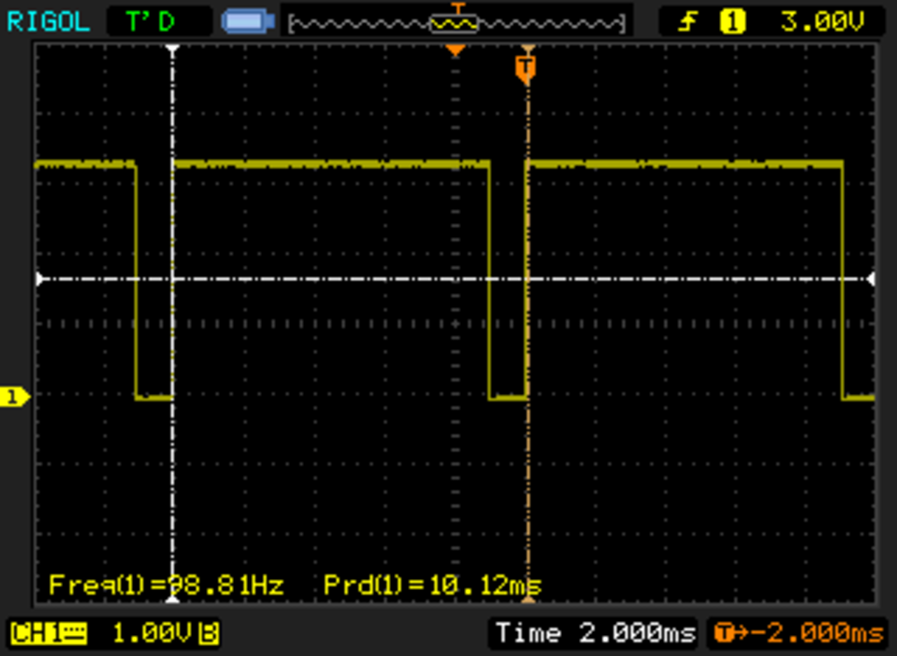
Now she could alter these - set the on time to 0.1, and the off time to 0.9. We were able to see such a change on the oscilloscope, and the LED was brighter.
I then suggested we can make a variable called duty_cycle, which we could alter to change both these variables at once. This snippet is only the variables section - the rest stays the same:
frequency = 100
duty_cycle = 0.4
on_time = duty_cycle/frequency
off_time = (1 - duty_cycle)/frequency
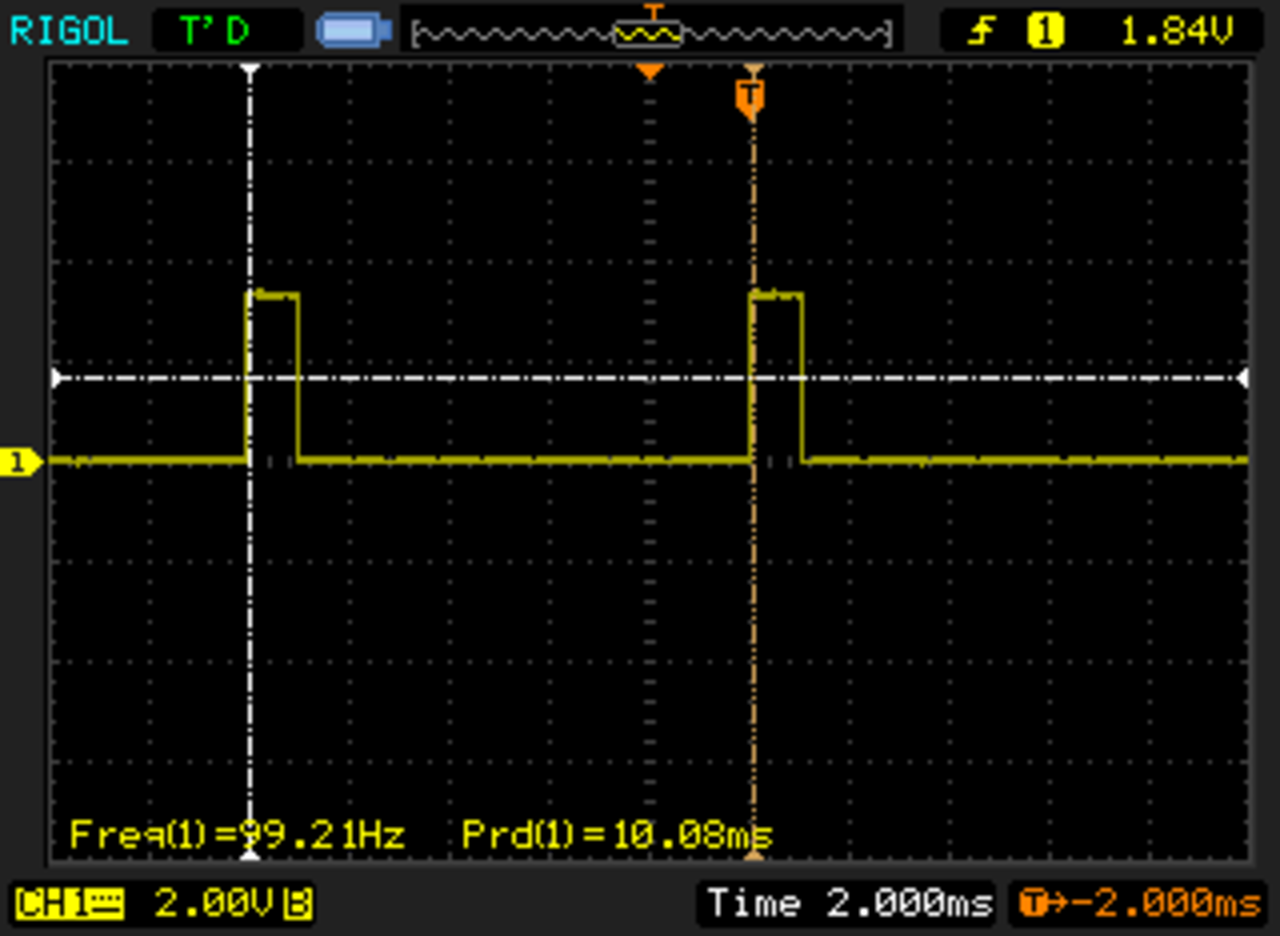
With this, she was able to change duty cycle, and with the oscilloscope dialled in to get 5 divisions per cycle, we were able to clearly see the effect of this.
In this picture, she counted that 2/5 of the bars are full - this is 0.4.
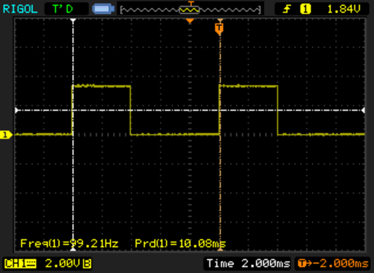
We then tried 0.9:
I explained how this is PWM (pulse width modulation), not sure she will remember the term, but I explained how it is how many motors are controlled - most of my robots use a principle like this, albeit controlled by hardware.
Turning this into tones
So now she was itching to get a sound out of this. And we had a quick way to do it. We have a little piezo speaker (not a buzzer) which fit nicely over the breadboard middle channel. It has a polarity noted, so Mini_orionrobots made sure that this was connected the right way, with a pin going down to grown, and another to Pin 15 (out monitor pin).
She was then able to start the code again, and hear a tone from the speaker! Awesome. We tried a few values. I remembered that 440hz was a musical note, and we tried it.
She tried adjusting the duty cycle - this does not set audio volume, and can have some other odd effects on the output. It made the tune change slightly, but no change in volume.
Making a noise maker
Mini_orionrobots was finished for the day, but I have also been playing with Raspberry Pi Pico as a noise maker. I intend to show Mini_orionrobots how to take her code further, so she can make whoops, whistles, and tunes on the device. I’ll show her how to use the built in PWM for somewhat more stable control, and a button to launch the sounds. An idea she had was to set up a dial (a potentiometer) to change the frequency, or a set of buttons like a keyboard.
We may even take this far further and into the realm of I2S (a sound output system). In principle, I could configure PIO pins to produce I2S output, I have an i2S amp and mic somewhere. This could give us more interesting ways to play with audio on the Raspberry Pi Pico.
Side Note
I also learned how to get screenshots from my new-ish Oscilloscope - the DS1052e. http://www.righto.com/2013/07/tips-for-using-rigol-ds1052e.html#:~:text=To%20take%20a%20screenshot%20on,This%20will%20save%20NewFile0. All those lovely screenshots from it were made this way.