Raspberry Pi Pico Wireless pack and Motors
Pimoroni have a wireless pack for Raspberry Pi Pico. This adds wifi capability with an ESP32 (and possibly bluetooth, more on that later). Wifi capability is great because it means I can teleoperate (remote drive) my robots, even if it’s just starting behaviors. In Learn Robotics Programming I have a chapter showing how to crate a nice web interface and remote camera/driving app to take advantage of Raspberry Pi 3a+ wifi. It’s something I’ve taken to adding to most of my robots. But what about Pico robots?
I could likely rig something up with an ESP-01 (based on the esp8266), but when Pimoroni had their Wireless Pack in stock, I had to try this out with one. The libraries in Micropython and CircuitPython already exist, the board can just be backpacked with Pico.
Great. But what about using it with a Kitronic Motor board too? Pico backpacks plug in to Raspberry Pi Pico, without further header extension pins for more packs. The motor board and wireless pack are included in this. Pimoroni do ship a 3 way (and 4 way) board allowing multiple packs, but I wanted to go a bit more raw.
Why more Raw?
First I am working on small robots, that don’‘t really have space for the 3 way pack. Space is at a premium (yes, the esp-01 might still be more suitable in that circumstance).
Second when using multiple packs together, there is no guarantee that pins won’t clash, which means I need to move things around a bit and reassign them. I’m prepared to override or modify software to allow this.
Thirdly if you use an extender, one of the motor board or the Wireless Pack end up upside down. The motor board requires access to the screw terminals to attach motors. The wireless pack has an LED, button and SD card slot - which I may want access to - however I’ll start with getting basic wifi working first. So they need to be at different orientations.
Electrical Connections
My plan for this is to keep Raspberry Pi Pico in the Kitronic Motor board. However, how can I then break out the connections to Pico?
I started by looking at the Pico Wireless Pack diagram on Pimoroni. This had many connections, but some were going to be for the SD card (which I could choose to bring into play later), a button, and additional esp32 functionality.
So I made some twitter enquiries, and Chris Parrot, currently at Pimoroni helped out.
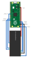
I turned his advice into a bare basics Fritzing Diagram:

Real Wiring
The real wiring is, I’ll admit a bit of a rats nest currently of Dupont cables going point to point. But 9 connections was enough to make this work. It powered on.

First attempt at code
I was able to setup CircuitPython 6.3.0, and copy over the adafruit_esp32spi library to the board (in the libs folder). Then using the pin instructions from Pimoroni and the CircuitPython page they directed me to, I was able to list access points no problem! So I know that the esp32 has worked properly.
As an aside, I like to use VSCode or Pycharm as editors. It’s a story for another time, but I’ve been using Invoke to manage libraries and code on CircuitPython.
Now it works, but what about the motors.
Getting motors working
So I have this already plugged into the motor board, as the photo above shows. However, to really test it, I need to add batteries and a motor. I grabbed some batteries in my robot cupboard, and a battery box. I’ve started with 3v from 2xAAA because I had them to hand. I may need something stronger later. I’ve wired in 1 gear motor - the yellow plastic gear motors, since I have so many of them about.
To check the pins I’d need to control this Kitronic board. I grabbed the datasheet. Looking at that datasheet, motor 1 is going to be just fine using GP2 and 3. Lets do the first motor.
Here is the wiring for the single motor.

I turned on the power switch, and the light lit up brighter here. This is a good sign.
Single motor code
Now I may again want to tone this down, but I’m going to try both directions on the motor straight out, without PWM. We can introduce PWM later when the basics are good.
First I import libraries to control the board, and time so I can have sleeps:
import board
from digitalio import DigitalInOut, Direction
import time
Then I set up the motor 1 pins:
motor1_a = DigitalInOut(board.GP2)
motor1_a.direction = Direction.OUTPUT
motor1_b = DigitalInOut(board.GP3)
motor1_b.direction = Direction.OUTPUT
The next part - I turn the motor in 1 direction, and stop in Coasting not braking mode:
motor1_a.value = 1
motor1_b.value = 0
time.sleep(1)
motor1_a.value = 0
motor1_b.value = 0
time.sleep(0.5)
So I can check the other pin, I then turn the motor the other way, also coasting.
motor1_a.value = 0
motor1_b.value = 1
time.sleep(1)
motor1_a.value = 0
motor1_b.value = 0
I finish this with a stop too. Disappointingly - the motor didn’t move. Time to crack out the multimeter - lets check the batteries (may be weak) and the motor connections.
Multimeter Checks
I start in voltage - just how old are the batteries - I did rummage, and get a couple of batteries conveniently in a box, which may have been used for a microbit badge… Ahem. So what is that reading… My multimeter is a manual Uni-T UT50A. So I manually put it in in the 20V DC Range, and put it across the battery in terminals.


I get a perfect 3.0v. That is a bit sus. There’s no load. Does it stay that way if I let it run my code again? I use the serial port (via screen) and press CTRL-D to reload. No change. Okay - lets put it in continuity mode and check the motor connections.

I always like to tap the leads together in continuity mode - to check the beep. Dunno - it’s just a habit. Hmm - all the motor cables seem to work. What is going on here?

It could be that the voltage is too low, or it could be that my code isn’t right. Lets try the voltage measurement. I’m going to measure voltage across the two motor pins, start my code, and keep an eye on what I see. If I see 3v, that tells me that this motor is just too big for 3v, which is fairly likely. I can then try a bigger batteries. If not - then there may be another problem. Back to the 20v range. And run my code again.
This showed me 2.89v, then 0, then -2.89v, then 0. This confirms my code is working - but that I need bigger batteries. Time to rummage for those. The next battery box is 4xAA. I’ll check each on the way in to see that at least their no-load voltage is sane. After having 4 fresh AA batteries - which should be around 6v, this should move the motor.
Batteries in, light on.

Still nothing. Ok - this is odd. I’m going to try the motor directly across the batteries - does this motor work? Ive definitely driven them at 6v before. Total battery voltage - 5.88v. Still nothing. Hmm.
Clutching at straws, with the motor across the battery terminals, I try turning it - and it goes. Perhaps the axle had seized up a bit? I may have had these motors for a while, bu tI didn’t expect seizing in plastic motors. Let’s put it back.
And now it works - perhaps it would have worked at 3v - but I’m not going to go back.
Motor 2
So the next thing is 2 motors. So I wire in the second. And have to stop - it is immediately turning. Motor two is powered on. This is likely because it uses GP7, which is also the CS (chip select?) pin for the ESP32. That isn’t going to work. Let’s relocate that to an unused pin. This is where it’s clear the two boards wouldn’t have worked together without some sneaking.
Perhaps I can just move to a pin neither board uses? Pin 31, GP26 looks viable.

I cautiously wire it back in - and boom, it’s not turning continuously.

Before I make motor 2 test code - I need to make sure the wi-fi AP scan still runs. I swap GP7 for GP26 here and rerun. And it succeeds! I have an AP list.
esp32_cs = DigitalInOut(board.GP26)
esp32_ready = DigitalInOut(board.GP10)
esp32_reset = DigitalInOut(board.GP11)
The motor 2 code - I’ll take a copy of the motor 1 code, and update the pin numbers and variable names. There should be nothing surprising here.
This works too!
Can we drive motors and scan wifi together
This may seem like a silly demo, but if we are going to teleoperate a robot, we must be able to have motors running with the wireless active. So going to write a mash up of the last 3 demonstrations:
motor 1 fwd
scan ap
stop
motor 1 reverse
motor 2 fwd
scan ap
motor 2 reverse
scan ap
stop
Although i’ll stick to script-like initialisation, I’ll make myself some helper functions to match the pseudo-code above. These are horrid proof of concept code using globals - but they’ll do to try this out. Notice the print statements so I can keep tabs of what is going on.
def motor_1_fwd():
    print("motor_1_fwd")
    motor1_a.value = 1
    motor1_b.value = 0

def motor_1_rev():
    print("motor_1_rev")
    motor1_a.value = 0
    motor1_b.value = 1

def motor_1_stop():
    print("motor_1_stop")
    motor1_a.value = 0
    motor1_b.value = 0

def motor_2_fwd():
    print("motor_2_fwd")
    motor2_a.value = 1
    motor2_b.value = 0

def motor_2_rev():
    print("motor_2_rev")
    motor2_a.value = 0
    motor2_b.value = 1

def motor_2_stop():
    print("motor_2_stop")
    motor2_a.value = 0
    motor2_b.value = 0

def all_stop():
    print("all_stop")
    motor_1_stop()
    motor_2_stop()

def scan_ap():
    print("scan_ap")
    for ap in esp.scan_networks():
        print("\t%s\t\tRSSI: %d" % (str(ap['ssid'], 'utf-8'), ap['rssi']))
We then have an initialisation section - to set up pins and prepare all the devices:
print("Setting up devices")
motor1_a = DigitalInOut(board.GP2)
motor1_a.direction = Direction.OUTPUT
motor1_b = DigitalInOut(board.GP3)
motor1_b.direction = Direction.OUTPUT
motor2_a = DigitalInOut(board.GP6)
motor2_a.direction = Direction.OUTPUT
motor2_b = DigitalInOut(board.GP7)
motor2_b.direction = Direction.OUTPUT

esp32_cs = DigitalInOut(board.GP26)
esp32_ready = DigitalInOut(board.GP10)
esp32_reset = DigitalInOut(board.GP11)

spi = busio.SPI(board.GP18, board.GP19, board.GP16)
esp = adafruit_esp32spi.ESP_SPIcontrol(spi, esp32_cs, esp32_ready, esp32_reset)


if esp.status == adafruit_esp32spi.WL_IDLE_STATUS:
    print("ESP32 found and in idle mode")
print("Firmware vers.", esp.firmware_version)
print("MAC addr:", [hex(i) for i in esp.MAC_address])
Finally we can write our pseudo-code as real code. With sleeps.
print("Starting test")
motor_1_fwd()
scan_ap()
time.sleep(1)
all_stop()
time.sleep(0.5)
motor_1_rev()
motor_2_fwd()
scan_ap()
time.sleep(1)
all_stop()
time.sleep(0.5)
motor_1_stop()
motor_2_rev()
scan_ap()
time.sleep(1)
all_stop()
print("Test complete")
This kind of works, although the sleep may have been unnecessary because of the AP scan taking a while.
I think I’ll leave this for now. The next step on this is to try PWM on the pins for the motor. I don’t think Kitronik would have chosen pins that couldn’t, and it should be able to handle PWM while doing an AP scan.